Gas turbine engine with a gearbox-mounted starter

A gas turbine and engine technology, applied in gas turbine installations, machines/engines, engine components, etc., can solve problems such as oil leakage, and achieve the effect of reducing the risk of emptying

Active Publication Date: 2008-08-06
HISPANO SUIZA SA
View PDF1 Cites 7 Cited by
  • Summary
  • Abstract
  • Description
  • Claims
  • Application Information

AI Technical Summary

Problems solved by technology

If this occurs, the leakage of lube oil supplied to the starter via the filter from the auxiliary gearbox case remains insignificant

Method used


Image

  • Gas turbine engine with a gearbox-mounted starter
  • Gas turbine engine with a gearbox-mounted starter

Examples


Embodiment Construction

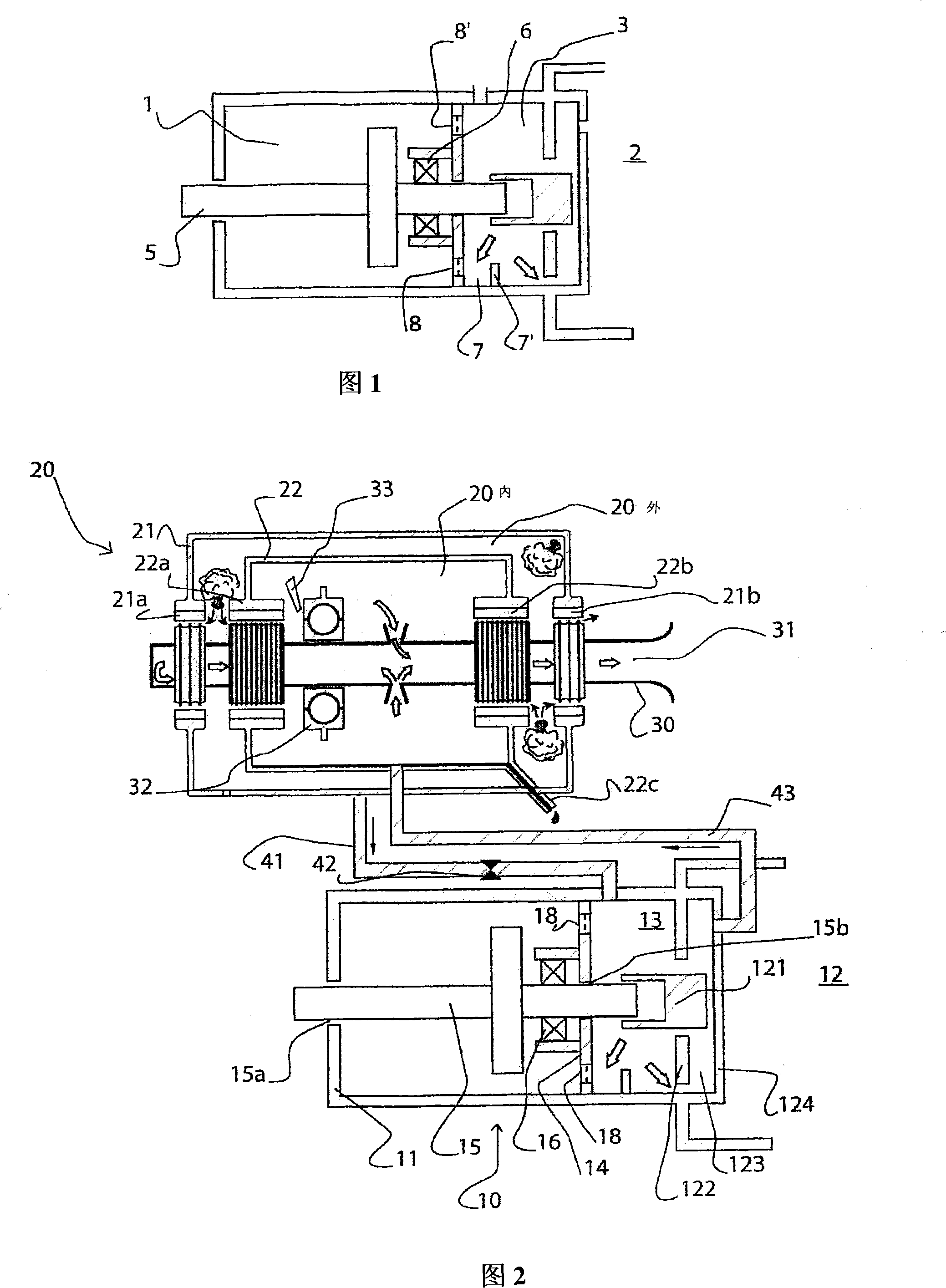
[0018] Referring now to FIG. 2, FIG. 2 is a schematic diagram of a typical arrangement according to a first embodiment of the present invention.

[0019] Starter 10 includes a closed housing 11 for supplying lubricant to the rotating components of starter 10 , representatively a rotating assembly or shaft 15 rotatably mounted within housing 11 via bearings 16 . It should be understood that associated with this rotating assembly are associated pinions, reduction gears, fuses and other components that make up the starter. Since the present invention does not aim at the structure of the starter, the situation of the structure of the starter will not be further described in detail. This rotating assembly 15 is connected to one side of an air turbine, not shown. When the turbojet is started, the turbine turns the rotating assembly 15 in rotation. Turbine seal 15 a provides a seal between rotating assembly 15 and casing 11 . On the other hand, the rotating assembly passing throug...


PUM


Abstract

The engine has an auxiliary gearbox (12) connected mechanically to a shaft (30) of the engine for driving auxiliary machines. An air starter (10) having an oil enclosure is mounted on the gearbox, where the oil enclosure and the gearbox are communicated with each other such that lubricating oil in the starter is distributed from the gearbox. The oil enclosure is pressurized by an air source e.g. bearing's pressurization enclosure, that is independent from the gearbox. An air return conduit (43) is connected on a wall (124) of the gearbox.

Description

technical field [0001] The invention relates to the field of gas turbine engines, in particular turbojet engines. Furthermore, the present invention particularly relates to air starters mounted on power transmission gearboxes. Background technique [0002] The turbojet engine consists of a box fixed to the outer casing, in which are arranged a plurality of pinions, mechanically connected to the engine shaft, thereby driving the engine shaft in rotation. However, these pinions are in turn connected to equipment that assists the engine, such as a pump or an electrical generator that supplies power to the engine. More specifically, this box supports the starter, for example, especially when starting on the ground, it can mechanically drive the engine shaft to rotate, and belongs to the high-pressure rotor part of the multi-body engine. The case is usually referred to as AGB, an acronym for "auxiliary gearbox". Lubrication of the rotating parts within the starter housing is n...

Claims


Application Information

Patent Timeline
Patent Type & Authority Applications(China)
IPC IPC(8): F01D25/18F02C7/277
CPCF02C7/277F01D25/18
Inventor 彻勒奥·安维拉让-路易斯·查伯纳尔玛丽-莱斯·达德恩科里恩·弗罗尼尔皮埃尔·莫顿
Owner HISPANO SUIZA SA
Why Eureka
Try Eureka