
Imaging apparatus and assembling method of imaging apparatus

A technology of camera device and image square, applied in installation, image communication, components of color TV, etc., can solve the problem of increasing radial size and other problems

Inactive Publication Date: 2008-08-06
KONICA MINOLTA OPTO
View PDF4 Cites 23 Cited by
  • Summary
  • Abstract
  • Description
  • Claims
  • Application Information

AI Technical Summary

Problems solved by technology

[0006] The imaging device disclosed in Patent Document 2 also has a large radial dimension due to the arrangement of the drive mechanism for driving the lens outside the lens group constituting the imaging lens.

Method used


Image

  • Imaging apparatus and assembling method of imaging apparatus
  • Imaging apparatus and assembling method of imaging apparatus
  • Imaging apparatus and assembling method of imaging apparatus

Examples


Embodiment 1

[0093] The lens data of Example 1 suitable for the first embodiment are shown in Table 1 and Table 2. After this (including the lens data in the table) multiply the power of 10 (for example, 2.5×10 -3 ) is represented by E (for example, 2.5E-3).

[0094] [Table 1]

[0095] f=4.69mm, fB=0.64mm, F=3.29, 2Y=5.63mm

[0096] face number

R(mm)

D(mm)

Nd

vd

Aperture stop

0.00

1

3.268

1.05

1.53180

56.0

2

-2.759

0.10

3

16.098

0.60

1.58300

30.0

4

1.823

0.70

5

-10.205

1.14

1.53180

56.0

6

-1.500

0.10

7

3.580

0.72

1.53180

56.0

8

1.129

A (variable interval)

9

0.50

1.51633

64.1

10

[0097]

[0098] Object distance ∞: A=0.63mm

[0099] Object distance 10...


PUM


Abstract

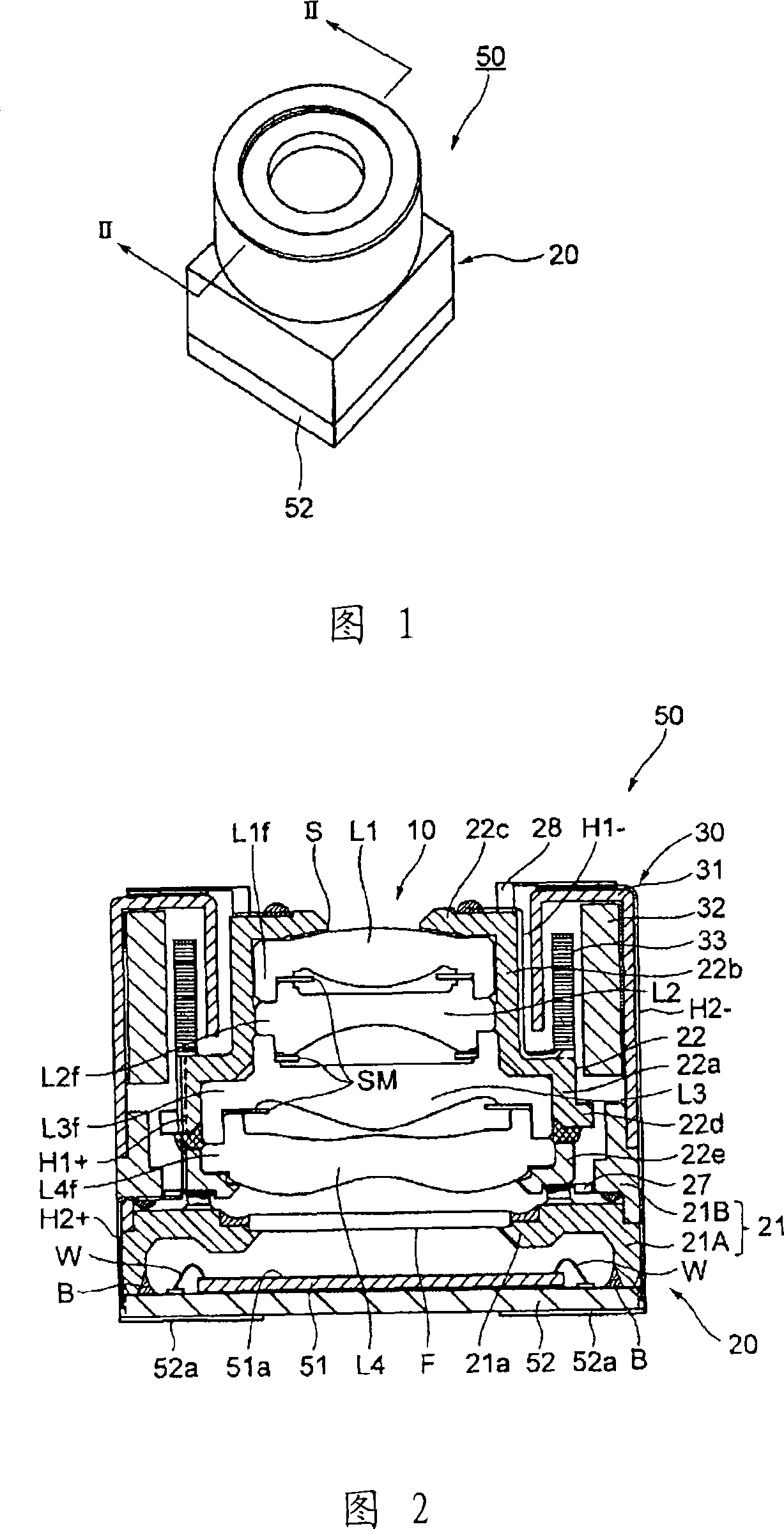
In order to provide an imaging device capable of performing a focusing operation and having a more compact structure, the driver is disposed in the space around the minimum effective aperture lens caused by the difference between the outer diameter of the minimum effective aperture lens and the maximum effective aperture lens. At least a part of the driver is used to drive the moving focusing lens group during focusing, thereby manufacturing a compact imaging device with increased driving force.

Description

technical field [0001] The present invention relates to a compact imaging device using a solid-state imaging device such as a CCD image sensor or a CMOS image sensor, and more particularly to an imaging device equipped with an autofocus mechanism and a method for assembling the imaging device. Background technique [0002] In recent years, as the performance of imaging devices using solid-state imaging elements such as CCD (Charge Coupled Device) image sensors and CMOS (Complementary Metal Oxide Semiconductor) image sensors has increased, a number equipped with an autofocus mechanism has been installed. (hereinafter referred to as AF mechanism) mobile phones with imaging devices are spreading. Furthermore, there is an increased demand for further miniaturization of these imaging devices. As an imaging device having such an AF mechanism, Patent Document 1 and Patent Document 2 disclose, for example. [0003] Patent Document 1: (Japanese) Unexamined Patent Publication No. 20...

Claims


Application Information

Patent Timeline
Patent Type & Authority Applications(China)
IPC IPC(8): G02B7/04G02B7/02G02B7/08H04N5/225
Inventor 山口进佐藤正江铃木裕介
Owner KONICA MINOLTA OPTO
Learn More