
Sliding chute positioning link bar

A connecting rod and chute technology, which is applied to building components, covering/lining, construction, etc., can solve the problems of high cost, difficulty, sale or scrap of old furniture, etc., and achieve the effect of reducing cost, improving efficiency, and flexible assembly and disassembly

Inactive Publication Date: 2010-06-02
王君
View PDF8 Cites 0 Cited by
  • Summary
  • Abstract
  • Description
  • Claims
  • Application Information

AI Technical Summary

Problems solved by technology

The time-consuming, material-intensive, low-efficiency, and high-cost problems of home decoration have always been important problems that people feel cannot be overcome at present. What's more, for buildings that have been renovated and used for several years, it is almost a one-time job to replace the decoration style and style. It is very difficult and impossible to realize the problem, especially the built-in furniture manufactured along with the interior decoration process.
The damage caused by long-term use can only be solved by partial repair
Although mobile furniture can be replaced with new ones, old furniture has to be sold or scrapped

Method used


Image

  • Sliding chute positioning link bar
  • Sliding chute positioning link bar
  • Sliding chute positioning link bar

Examples


no. 1 example

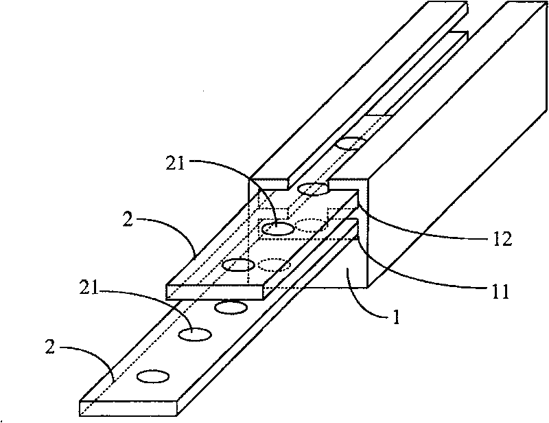
[0044] figure 1 Shown is a basic embodiment of the present invention, which includes a cylinder 1, and the surface of the cylinder 1 is provided with a double-layer chute group composed of a lower chute 11 and an upper chute 12 superimposed. The lower floor chute 11 and the upper floor chute 12 are linear chutes whose inner width dimension is greater than the notch width dimension, and its cross-sectional shape is "convex". The notch of the lower floor chute 11 is located at the bottom of the upper floor chute 12 . Two sliding sheets 2 are matched in the lower chute 11 . A slide plate 2 is matched in the upper chute 12 . Sliding plate 2 can only slide linearly in the double-layer chute group. The sliding sheet 2 is also provided with a plurality of screw holes 21 for fixing the sliding sheet 2 and external mounting parts by bolts.

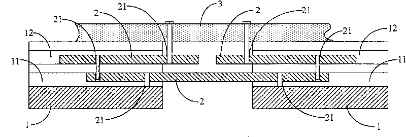
[0045] The basic purposes of the lower chute 11, the upper chute 12 and the slide 2 are as follows: figure 2 shown.

[0046] figure 2 Amo...

Embodiment 2

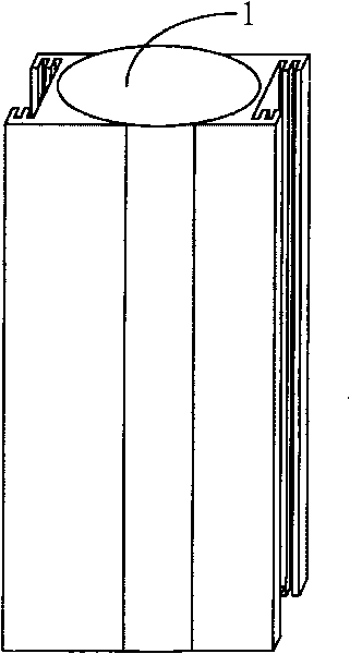
[0050] image 3 Shown is an embodiment with two double chute sets. In this embodiment, the cross-sectional shape of the cylinder 1 is circular. The setting directions of the two double-layer chute groups are in the same direction, and adopt a symmetrical manner. When the keel bracket is formed in this embodiment, since there are two sets of double-layer chute groups arranged symmetrically, other components, such as plates and other devices, can be installed and fixed in two directions of the keel bracket.

Embodiment 3

[0052] Such as Figure 4 As shown, the difference between this embodiment and the above-mentioned second embodiment is that: the cross-sectional shape of the cylinder 1 is an annular rectangle; 11. The lower chute 11 is provided with a sliding piece 2 . The two lower chutes 11 are also arranged symmetrically, so that there are chutes on the surface of the cylinder composed of four sides, of which two are double-layer chute groups, and the other two are lower chute 11. . The hollow cylinder 1 can save a lot of raw materials, especially when the cylinder 1 is manufactured in large quantities by extruding non-ferrous metals.

[0053] In this embodiment, the state when a plurality of cylinders are axially connected is as follows: Figure 5 shown. exist Figure 5 Among them, since two adjacent cylinders 1 have lower sliding grooves 11, four sliding pieces 2 can be used for axial connection, so that the connection strength is greatly improved. In addition, when using this embo...


PUM


Abstract

The present invention relates to a sliding chute locating connecting rod comprising a cylinder body, the surface of the cylinder body is arranged with a double layer sliding chute group overlapped bya lower siding chute and an upper sliding chute; the lower sliding chute and upper sliding chute are all straight line shaped sliding chute with inner breadth dimension larger than the notch breadth dimension; the notch of the lower sliding chute is arranged at the bottom of the upper layer; the lower sliding chute and the upper sliding chute are all matched with one or a plurality of sliding vanes which can only slide in the double-layer sliding chute group, and the sliding vane is arranged with a plurality of screw holes which fix the sliding vane and the exterior installing component with abolt. The invention uses the arranged double-layer sliding chute group and the sliding blades with screw for locating and fixing between each other, the on-site quick installation of various keel brackets can be realized and the invention has the advantages of random stepless dimension adjustment, flexible assembling-disassembling function, without any noise, greatly increasing the velocity of decoration and manufacturing, overcoming the various defects existing in the traditional decoration and furniture manufacturing technique.

Description

technical field [0001] The invention relates to a chute positioning connecting rod, in particular to a beam column capable of forming a keel bracket for construction, decoration and furniture manufacturing, and realizes the positioning and connection of various parts on the keel bracket through the chute, and can realize the length Connecting rods with adjustable dimensions. Background technique [0002] In traditional indoor and outdoor building decoration and furniture manufacturing, various frame structures are usually required. For solid wood and metal furniture, the frame structure is to connect the supporting skeleton materials through mortise and tenon to form the main frame of the furniture, and then use plates or other materials for packaging and internal separation, and finally complete the furniture manufacturing. For building walls (including laying wallboards and partition walls on the walls), this kind of supporting skeleton material is also used to carry out ...

Claims


Application Information

Patent Timeline
Patent Type & Authority Patents(China)
IPC IPC(8): E04F13/07E04B9/06
Inventor 王君
Owner 王君
Learn More