
Curtain plate type roller-blind door

A kind of rolling shutter door, curtain plate technology

Inactive Publication Date: 2012-06-13
KOMATSU ELECTRIC SANGYO
View PDF1 Cites 0 Cited by
  • Summary
  • Abstract
  • Description
  • Claims
  • Application Information

AI Technical Summary

Problems solved by technology

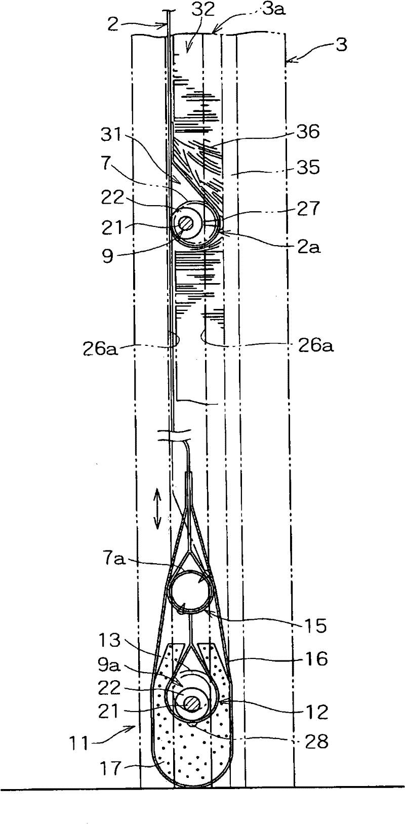
[0006] However, in the above-mentioned curtain-type rolling door, the core material, the both sides of the counterweight core material and the buffer core material are inserted into the guide grooves of the pillars for support, so when the curtain plate is lowered, the grounding part abuts against the abutment. When the curtain plate is in contact with the abutting object and is restricted, it descends, so that the upper counterweight core material and the core material will sequentially abut the flexible core material, and the whole becomes inclined to one side. state
[0007] In addition, in the state where the core materials are in contact with each other and tilted, if the contact load continues to act, the flexible core material, the counterweight core material, and the side ends of the core material will contact and interfere with each other. If the load in the front-back direction is further applied, the flexible core material and weight core material will become difficult or impossible to disengage from the guide groove, which may cause damage to the core material, guide rails, or pillars, etc.
[0008] Therefore, the following scheme has been tried, that is, on both sides of each core material, a core material support member whose breaking strength is set by plastic molding is detachably provided, and it is inserted into the guide groove to displace it. However, even with this solution, if the core materials are assembled and their core support members interfere with each other, it will be difficult to escape from the guide groove.

Method used


Image

  • Curtain plate type roller-blind door
  • Curtain plate type roller-blind door
  • Curtain plate type roller-blind door

Examples


Embodiment Construction

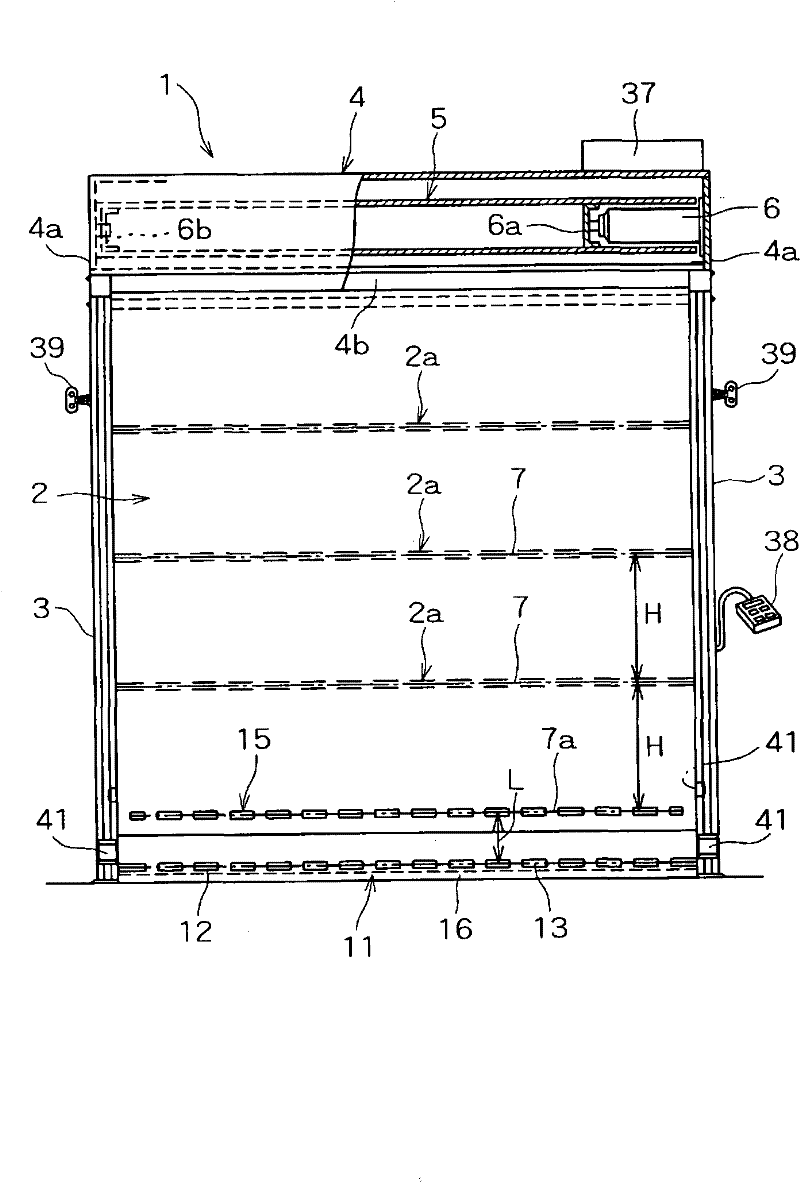
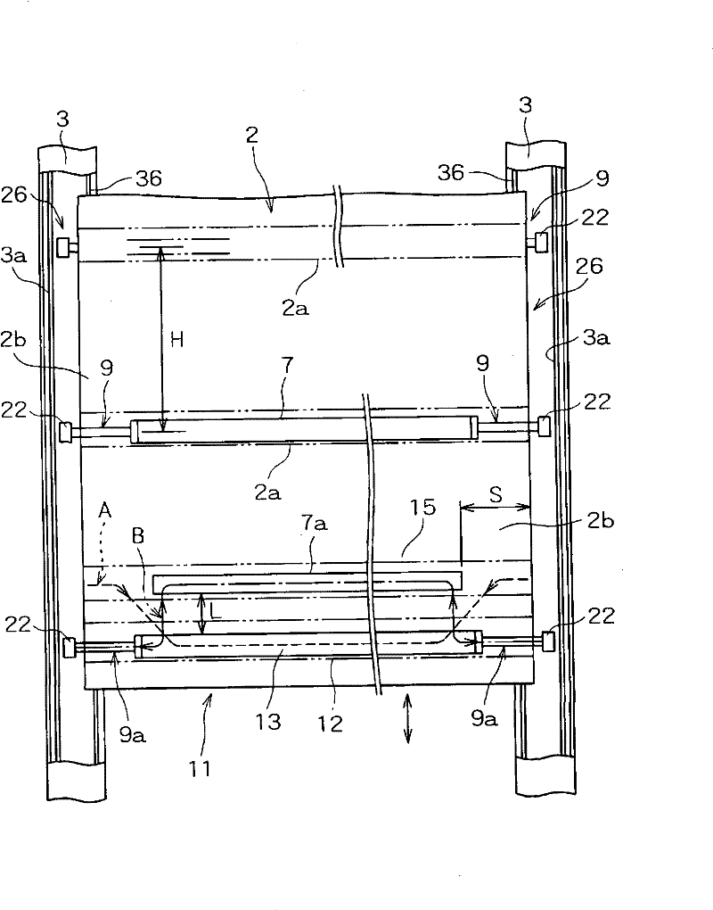
[0027] Next, one embodiment of the present invention shown in the drawings will be described. exist figure 1 , figure 2 Among them, reference numeral 1 is a curtain type rolling door of the present invention, and the entrance and exit are opened and closed by moving a curtain (door) 2 up and down on a door frame erected at an entrance (front opening) of a building or the like. The door frame of the curtain type rolling door 1 is formed into a door-shaped frame by left and right pillars (side frames) 3, 3 and a hollow box-shaped curtain box 4, and the pillars 3, 3 are formed along the building pillars or The wall surface is erected and fixed to form a door installation opening (curtain opening and closing space), and the curtain box 4 is mounted and supported by connecting the upper parts of the pillars 3 and 3 .

[0028] The above-mentioned curtain box 4 is internally provided with a hollow cylindrical take-up drum 5 which is rotatable for taking up and unwinding the curtai...


PUM


Abstract

The present invention provides a curtain plate type rolling shutter, capable of quickly processing open-close action to the decreasing mobile force application, and capable of easing the pressing against fault when the grounding part presses against the jointing object. The invention relates to the improvement of the curtain plate type rolling shutter, characterized in that the grounding part setting of the curtain plate has flexible core material having flexibility and processing elasticity deformation, the upper of the flexible core material partitioning a pressing against buffer interval shorter than the core material configuration is parallelly mounted with a counterweight core material approximately which is more weight than the flexible core material and having rigidity. And the whole length of the counterweight core material is shorter than the core material inserting in and supporting the groove and the flexible core material, the two ends of the curtain plate of the two sidesof the counterweight core material of the curtain plate is provided with a side part having flexibility and supporting width of the core material, the side part in inserted in the groove to liftedly support and guide.

Description

technical field [0001] The present invention relates to a curtain-type rolling door installed at an entrance or a partition of a building such as a factory or a warehouse. Background technique [0002] Conventionally, there is known a curtain-type rolling door with a structure in which the front and back rotation of a motor is used to make a door curtain (シト) vertically installed at an entrance or a partition of a building such as a factory or a warehouse. A curtain-type rolling door that opens and closes by lifting up and down on the left and right pillars of the curtain. In the unwinding direction (length direction) of the curtain, a plurality of core materials that maintain the straightness of the front width direction are arranged, and above the grounding part of the curtain. A weight core material heavier than the above-mentioned core material is provided nearby, and a buffer core material having flexibility and elasticity to elastically deform is provided in the ground...

Claims


Application Information

Patent Timeline
Patent Type & Authority Patents(China)
IPC IPC(8): E06B9/15E06B9/58
Inventor 小松昭夫足立仁行堀江好明藤井雄志畑英树
Owner KOMATSU ELECTRIC SANGYO
Learn More