

Power battery module based on coupling cooling of loop heat pipe and phase change material
A technology of phase change materials and loop heat pipes, which is applied in the field of power batteries, can solve the problems of difficult manufacturing of spiral coils, low convective heat transfer coefficient, high cost, and high maintenance costs, so as to avoid excessive local temperature and compact overall structure , Efficient and uniform heat dissipation
- Summary
- Abstract
- Description
- Claims
- Application Information
AI Technical Summary
Problems solved by technology
Method used
Image

Examples
Embodiment Construction
[0038] The present invention will be described in further detail below in conjunction with the accompanying drawings and specific embodiments.
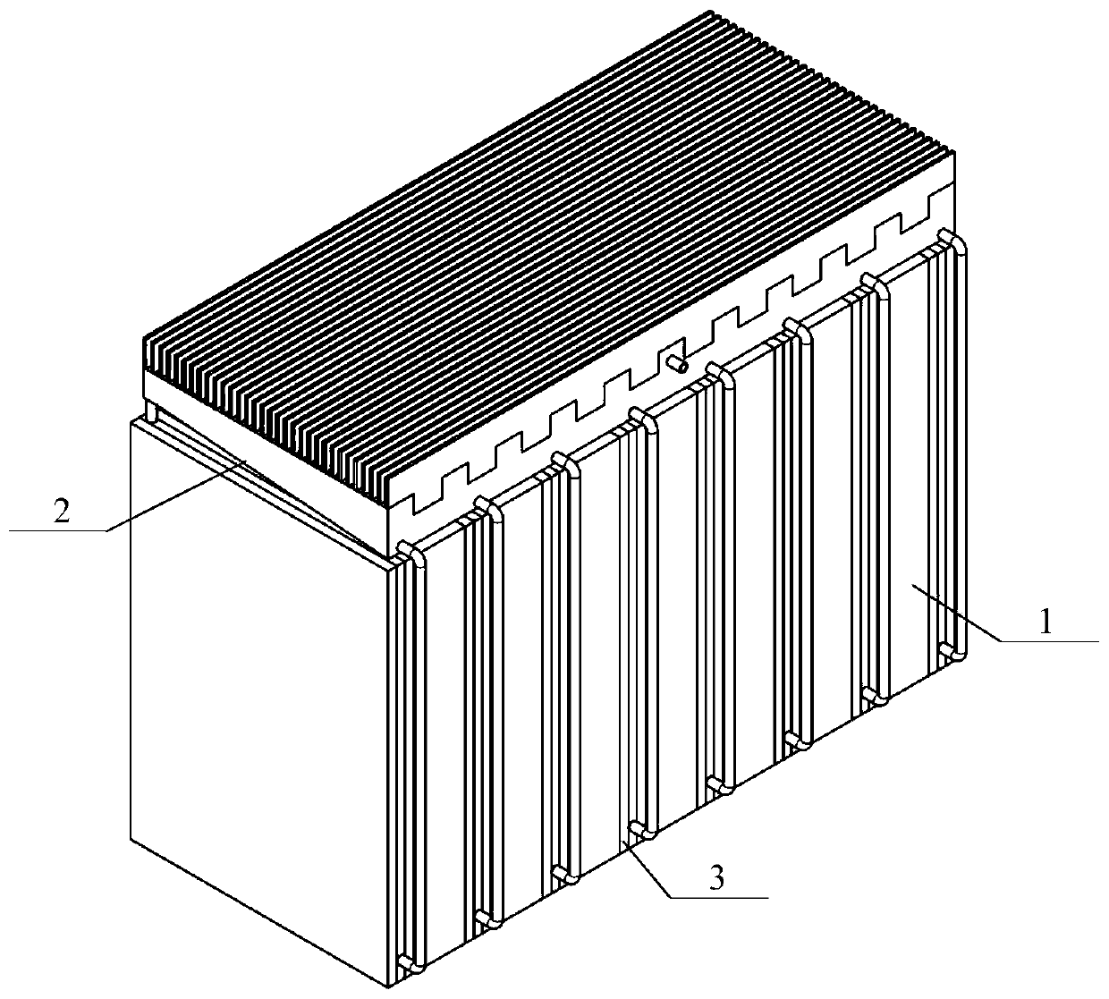
[0039] Such as Figure 1 to Figure 5 , Figure 8 As shown, the power battery module based on the coupled cooling of the loop heat pipe and the phase change material includes a battery module, a cooling system 2 and a phase change system;
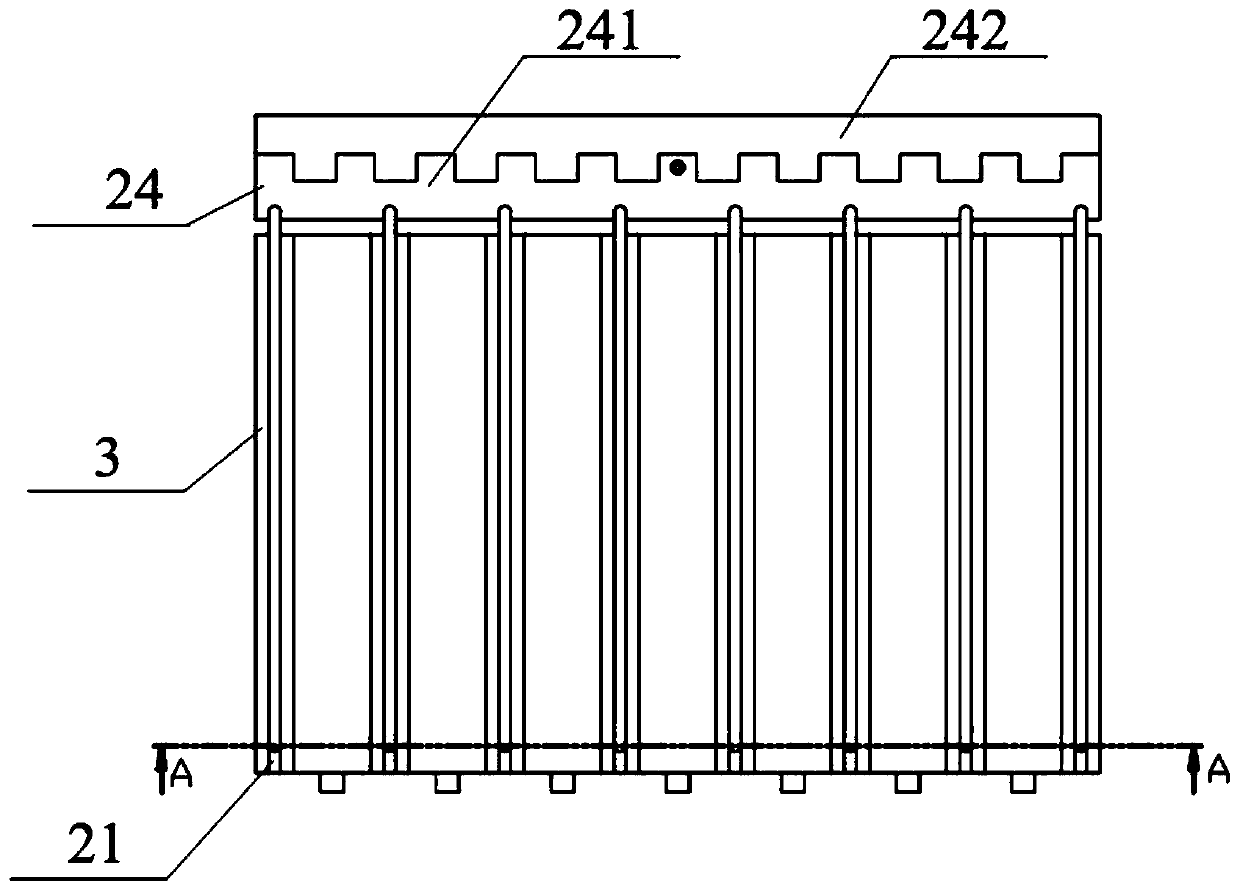
[0040] The cooling system 2 includes an evaporating plate 21 and a condenser 24; there are multiple evaporating plates 21, and the multiple evaporating plates 21 are arranged side by side with gaps left and right;
[0041] The phase change system includes a solid-solid phase change plate 3, and there are multiple solid-solid phase change plates 3, which are correspondingly arranged on the left and right sides of each evaporation plate 21;
[0042] The battery module includes a plurality of battery cells 1; each battery cell 1 is arranged between adjacent solid-solid phase change plates 3;
[0043...
PUM
 Abstract
Description
Claims
Application Information