Dual magnetic circuit electromagnetic microphone

An electromagnetic, microphone technology, applied in the field of microphones

Inactive Publication Date: 2008-08-13
TAIWAN CAROL ELECTRONICS
View PDF0 Cites 5 Cited by
  • Summary
  • Abstract
  • Description
  • Claims
  • Application Information

AI Technical Summary

Problems solved by technology

However, the condenser microphone needs a bias power supply to maintain the bias between the two electrodes of the

Method used


Image

  • Dual magnetic circuit electromagnetic microphone
  • Dual magnetic circuit electromagnetic microphone
  • Dual magnetic circuit electromagnetic microphone

Examples


Embodiment Construction

[0018] The present invention is described in detail below in conjunction with accompanying drawing and three preferred embodiments:

[0019] Before the present invention is described in detail, it is noted that in the following description, similar components are denoted by the same reference numerals.

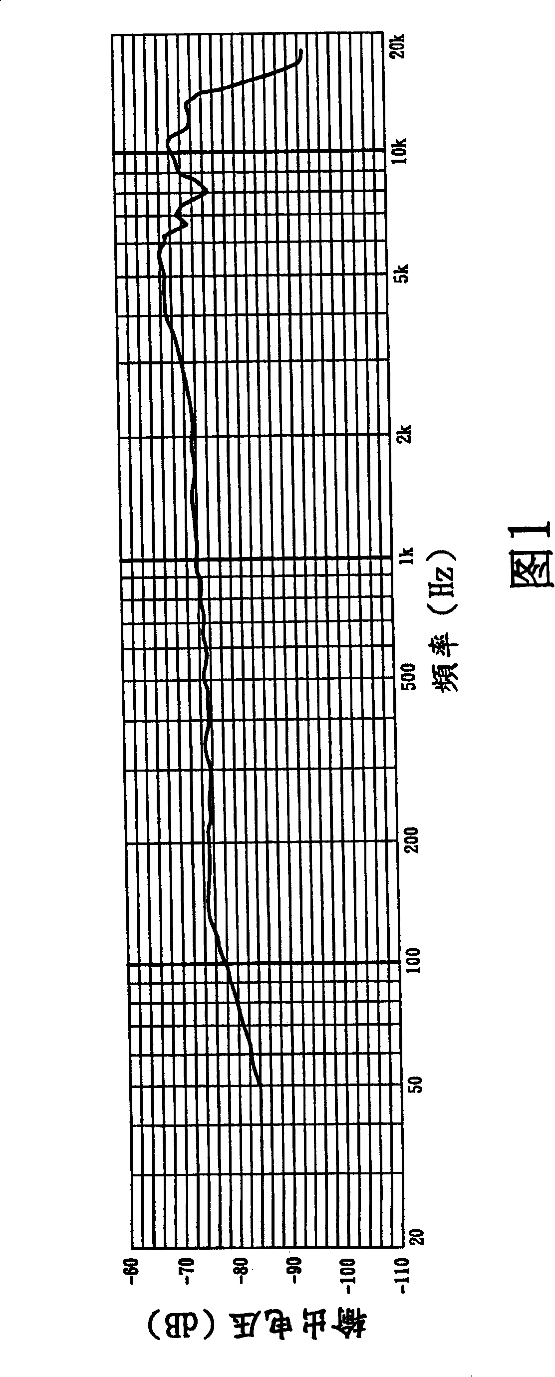
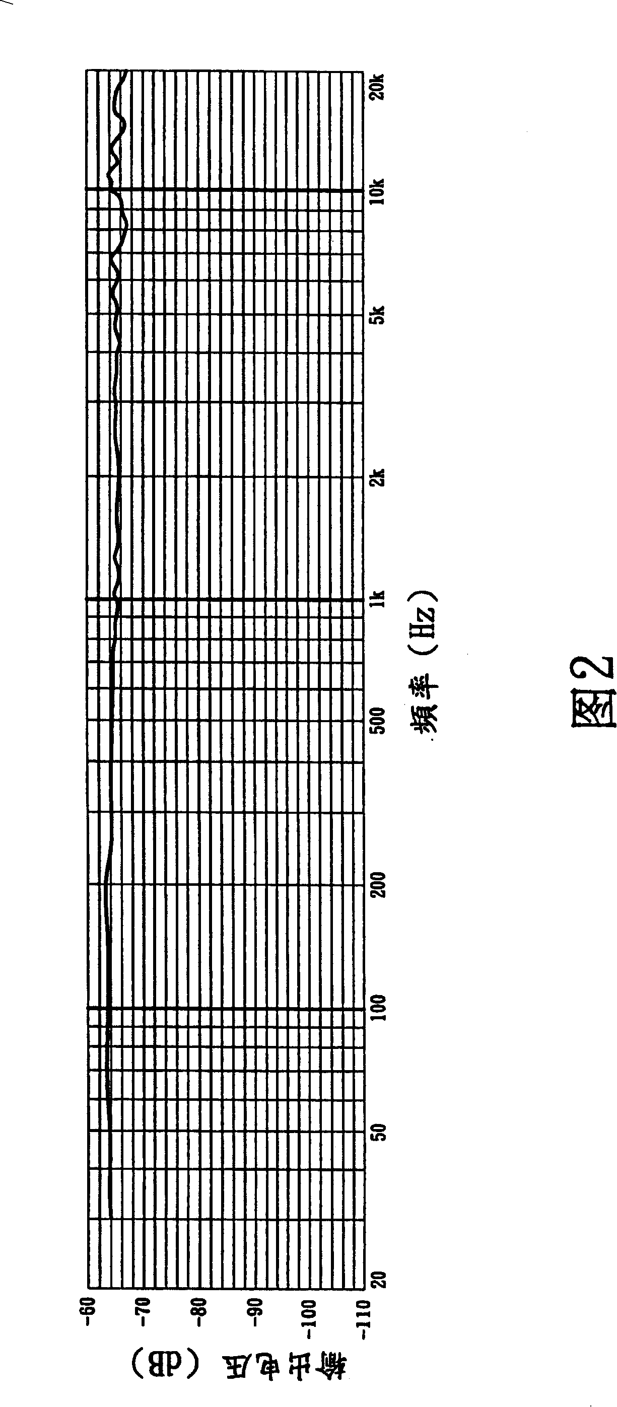
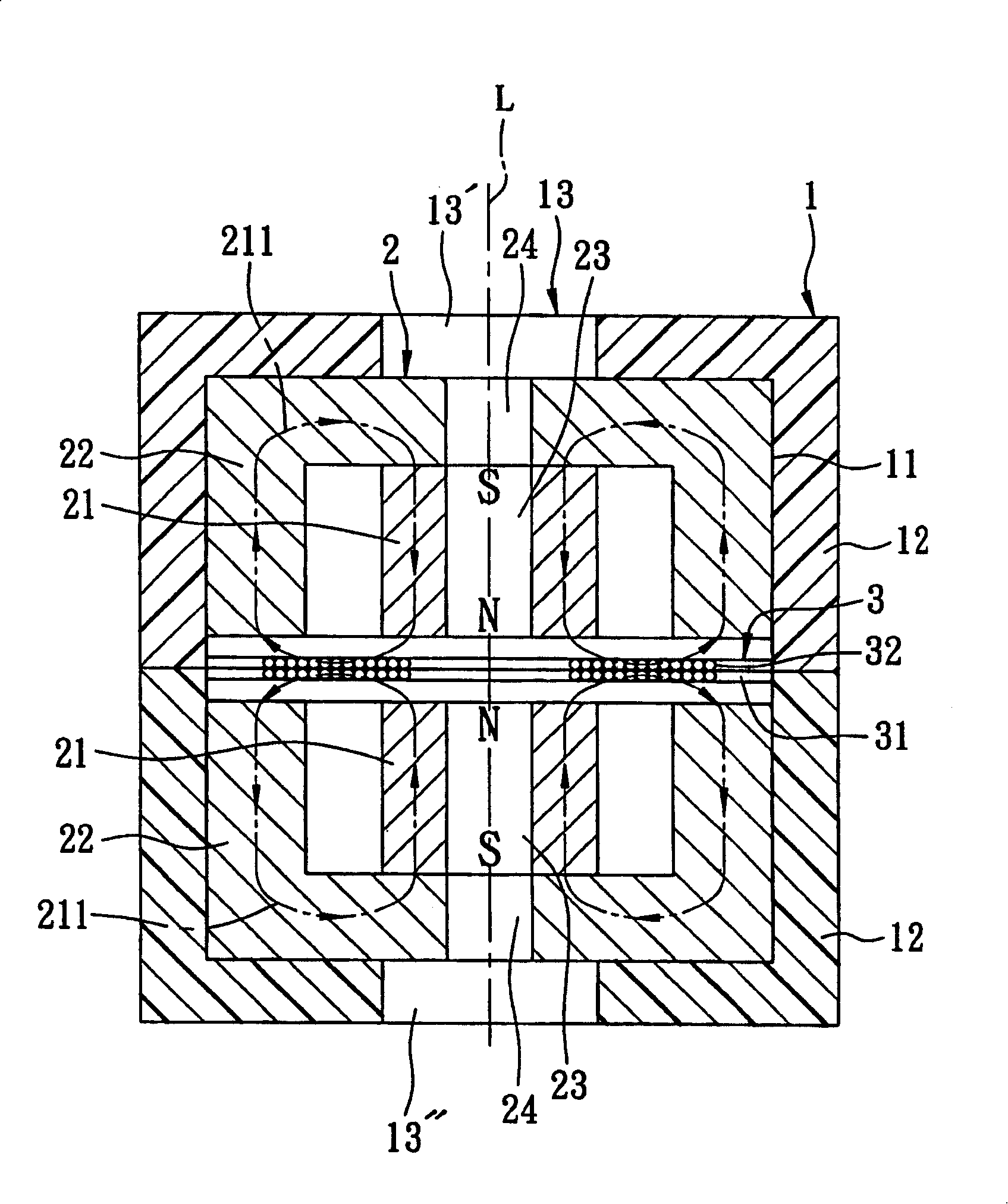
[0020] refer to image 3 , illustrating a first preferred embodiment of the dual magnetic circuit electromagnetic microphone of the present invention; this embodiment includes a housing unit 1, two magnetic units 2, and a response unit 3; wherein, the response unit 3 is inductive Vibration is generated by the sound wave pressure of a sound, and an electrical signal is output based on the electromagnetic effect due to being located in the magnetic fields respectively generated by the magnetic force units 2 .

[0021] The housing unit 1 includes two housings 12 that can cooperate with each other to define a chamber 11, and two through holes 13 respectively formed in the housings...


PUM


Abstract

A electro-magnetic microphone with double magnetic circuits, including a housing unit, two magnetic units, and one responding unit; wherein the housing unit includes two holes formed one two sides of the diaphragm; the magnetic unit is arranged in the housing unit and disposed one by one in one axis, wherein each magnetic unit includes a magnet generating multiple geomagnetic line, and one heel piece embracing the magnet and provides the mentioned geomagnetic lines; the response unit is provided with diaphragm disposed upward along the axis and between magnetic units, and a coil covering the diaphragm; thus, the inventive electro-magnetic microphone with double magnetic circuits has frequency response characteristic in both high and low frequency without use of bias power supply.

Description

technical field [0001] The invention relates to a microphone, in particular to a double magnetic circuit electromagnetic microphone. Background technique [0002] Since Edison invented the phonograph and recorded and reproduced sound in a scientific way, the reproduction of the original sound of the sound has always been a technical pursuit. Among them, the response characteristics of the microphone in the initial sound collection process determine everything; It can be divided into two categories according to the type of parts that respond to the sound: dynamic microphones and condenser microphones. [0003] The existing dynamic microphone includes a permanent magnetic field, a film-shaped diaphragm (Diaphragm), and a voice coil (Voice Coil) connected to the diaphragm and set in the permanent magnetic field. When a sound is transmitted to the diaphragm, the diaphragm will respond to the sound pressure of the sound to generate a vibration of a corresponding amplitude, and t...

Claims


Application Information

Patent Timeline
IPC IPC(8): H04R9/02H04R9/08
Inventor 张昭智蔡圳益
Owner TAIWAN CAROL ELECTRONICS
Why Eureka
Try Eureka