Recovery of energy in a hybrid vehicle comprising a hydraulic or pneumatic braking system

一种混合动力汽车、制动压力的技术,应用在混合动力车辆、通用动力装置的多个不同原动机的布置、制动传动装置等方向,能够解决最大电功率不能充分利用等问题

Inactive Publication Date: 2008-08-13
ROBERT BOSCH GMBH
View PDF0 Cites 21 Cited by
  • Summary
  • Abstract
  • Description
  • Claims
  • Application Information

AI Technical Summary

Problems solved by technology

This has a fundamental disadvantage that the maximum electrical power that can be produced by the generator is often not fully utilized

Method used


Image

  • Recovery of energy in a hybrid vehicle comprising a hydraulic or pneumatic braking system
  • Recovery of energy in a hybrid vehicle comprising a hydraulic or pneumatic braking system
  • Recovery of energy in a hybrid vehicle comprising a hydraulic or pneumatic braking system

Examples


Embodiment Construction

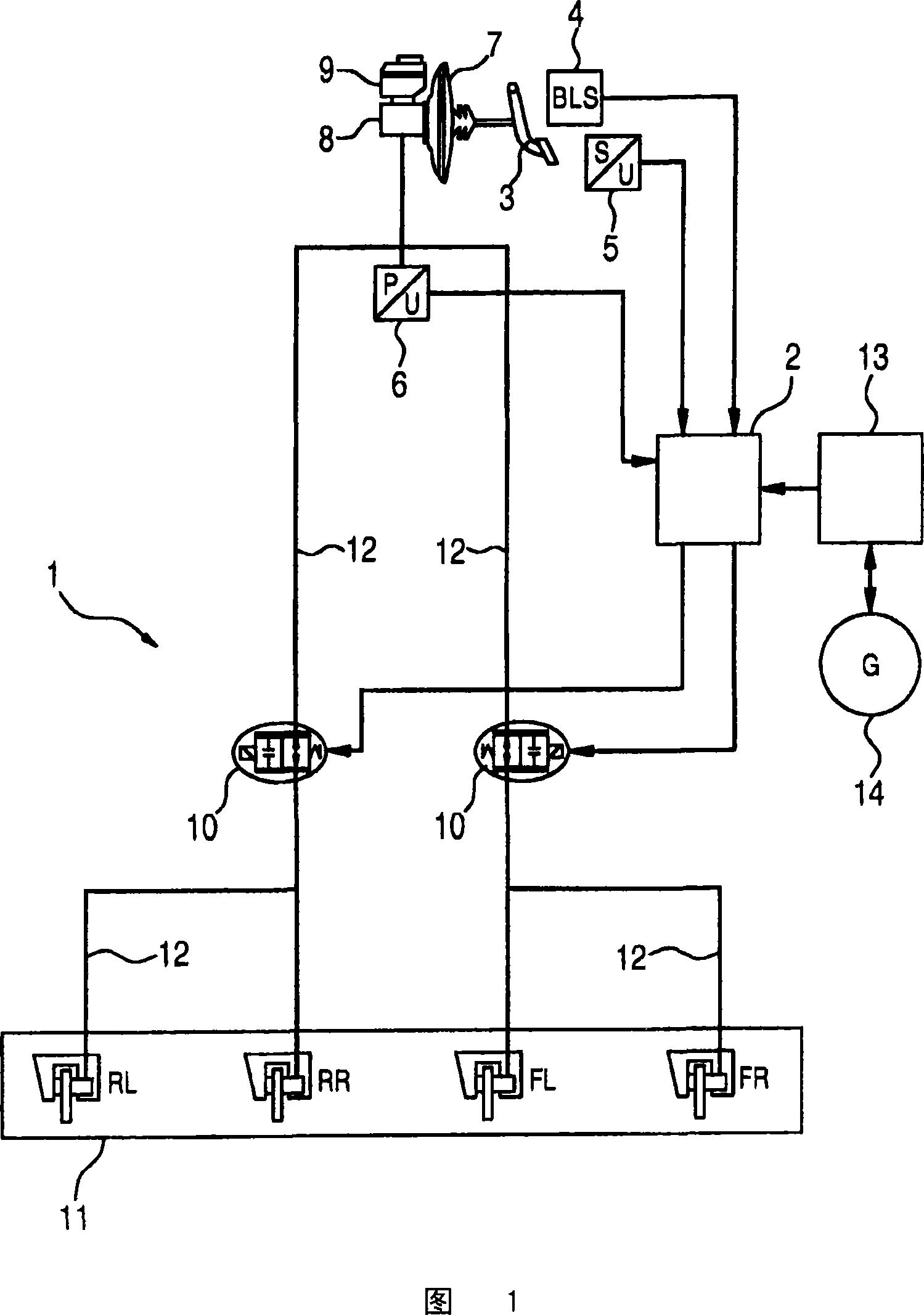
[0021] FIG. 1 shows a hydraulic vehicle brake system with a type II circuit distribution, the configuration of which is basically known from the prior art. As is known, the braking device 1 comprises a foot brake pedal 3, a brake booster 7 with a master brake cylinder 8 on which a brake fluid container 9 is arranged. . The brake booster 7 increases the braking force exerted by the driver on the foot brake pedal 3 and generates a brake pressure which is directed via the brake line 12 to the wheel brakes 11 .

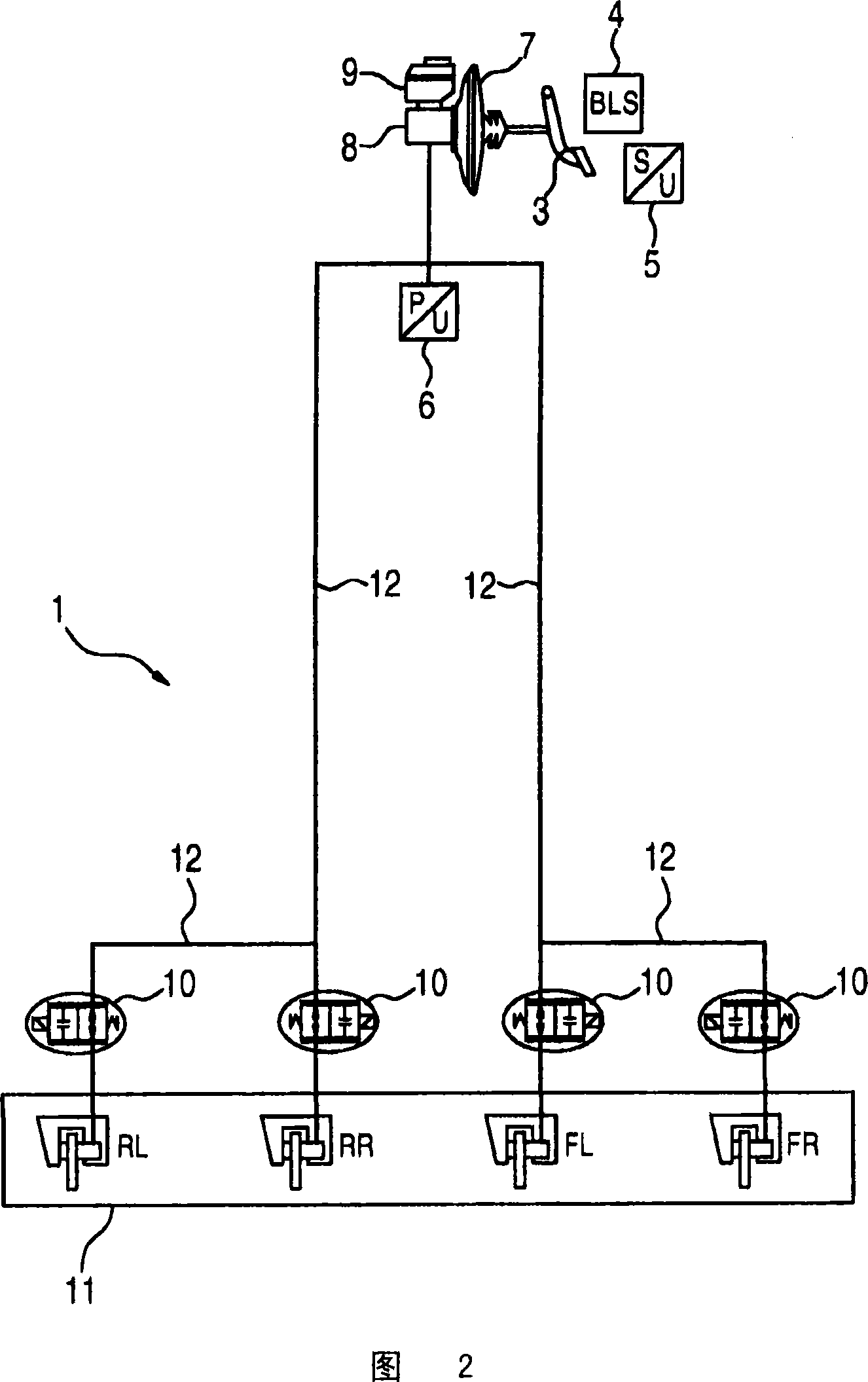
[0022] Unlike known braking devices, this brake device includes an additional valve 10, which is arranged in the main-brake line 12 of the driven axle and whose function is to reduce the force applied by the driver. brake pressure. Two valves 10 are shown here, of which only the left valve is installed in the case of rear-wheel drive, only the right valve is installed in the case of front-wheel drive, and both valves 10 are installed in the case of all-wheel drive. The...


PUM


Abstract

The invention relates to a method for recovering energy during a braking operation of a hybrid vehicle comprising an internal combustion engine and an electric drive (14), in addition to a hydraulic or pneumatic braking system (1). The use of the electric drive (14) can be optimised, if the braking system (1) comprises at least one pressure regulating valve (10), which is used to reduce the braking pressure exerted by the driver, in conjunction with the deceleration rate of the electric drive (14).

Description

technical field [0001] The invention relates to a method according to the preamble of claim 1 for recuperating (regenerating) energy during braking of a hybrid vehicle and a corresponding device according to the preamble of claim 6 . Background technique [0002] In a hybrid vehicle, the kinetic energy released during deceleration is typically converted to electrical energy and stored in the on-board power supply. Known regenerative systems for this use the electric drive as a generator. The alternator generates a tractive torque here to facilitate deceleration of the vehicle. The electrical energy thus obtained can be used in other driving states to drive the vehicle or to supply electrical loads. The efficiency of the car is thus significantly improved. [0003] Known regenerative systems are designed in such a way that the majority of the vehicle-deceleration is caused by the service brakes and only a small (depending on the state of the on-board power supply) by the a...

Claims


Application Information

Patent Timeline
Patent Type & Authority Applications(China)
IPC IPC(8): B60W30/18B60T13/58B60T8/176B60K6/48B60L50/16B60W10/18
CPCB60T1/10B60W10/184B60W30/18127B60K6/48Y02T10/92B60T2270/613B60W10/08Y02T10/6221B60W20/00B60T8/4275B60L7/18B60L7/26Y02T10/62B60T13/58B60W20/13
Inventor F·布罗克尔A·托斯特
Owner ROBERT BOSCH GMBH
Why Eureka
Try Eureka