Cleaning device for a textile machine

A technology for cleaning devices and textile machines, which can be used in deburring devices, textiles and papermaking, fiber processing, etc. It can solve the problems of impossibility of cleaning fiber materials and achieve the effect of removing and improving the cleaning effect

Inactive Publication Date: 2008-08-13
MASCHINENFABRIK RIETER AG
View PDF1 Cites 6 Cited by
  • Summary
  • Abstract
  • Description
  • Claims
  • Application Information

AI Technical Summary

Problems solved by technology

Therefore, it is basically impossible to form a cleaning of the sup

Method used


Image

  • Cleaning device for a textile machine
  • Cleaning device for a textile machine
  • Cleaning device for a textile machine

Examples


Embodiment Construction

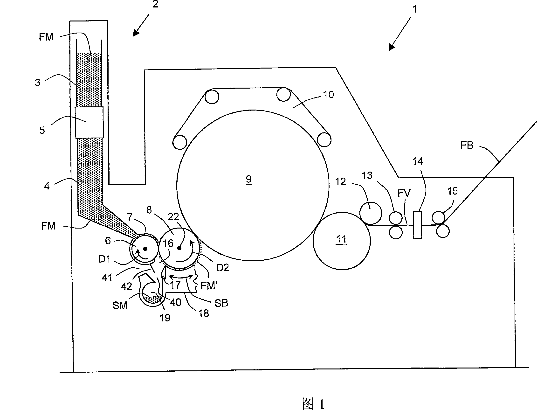
[0041] FIG. 1 shows a carding machine 1 as an example of a textile machine with a cleaning device. However, the invention can also be applied in other textile machines, in particular open-broom machines, such as coarse cleaners, fine cleaners or mixers, and also in spinning preparation machines, such as open-ended spinning machines.

[0042] The card 1 is designed for carding synthetic or natural fibers, in particular staple fibers, and fiber mixtures formed therefrom. The card 1 comprises a feed channel 2 which is only schematically shown here. The fibrous material FM prepared in the blowroom and in the form of coarse cotton tufts is fed into the feed channel 2 via an air flow by means of a pipe system not shown. In this case, the feed chute 2 comprises a feed trough 3 in its upper part, a storage trough 4 in its lower part and an opener device 5 interposed between them.

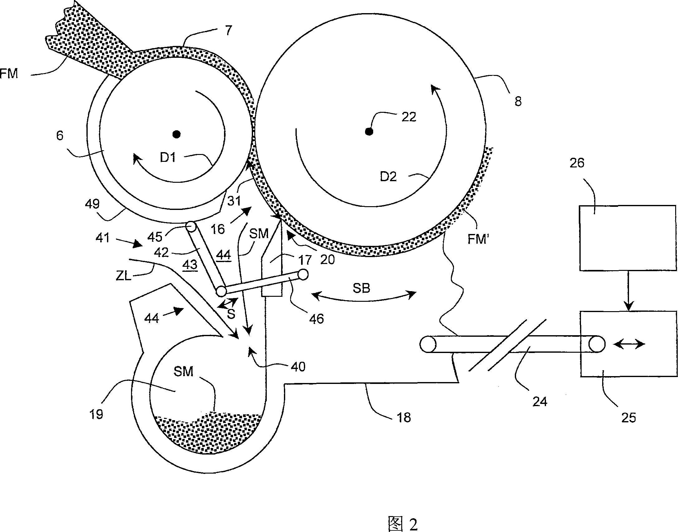
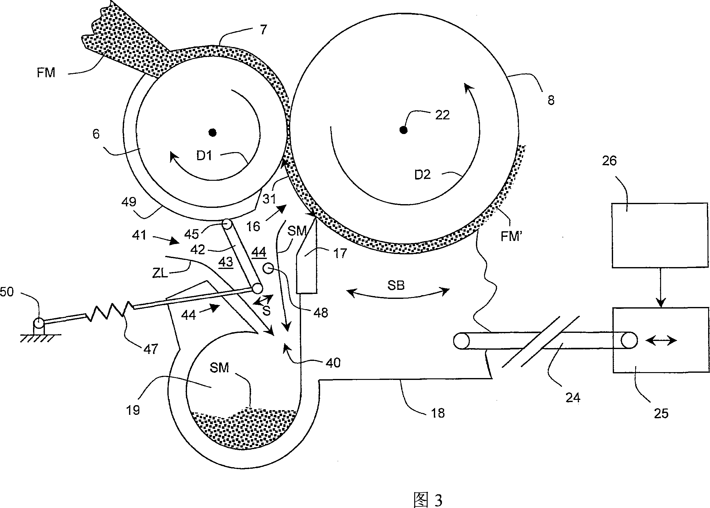
[0043] By opening the coarse fiber bundles in the opening device 5 , previously firmly bonded individu...


PUM


Abstract

Disclosed is a cleaning device for a textile machine (1), particularly a carding machine (1) or a blow room machine. Said cleaning device comprises a rotatable opening cylinder (8) for opening delivered fiber material (FM), e.g. a licker-in (8), and at least one dirt outlet (16) for eliminating dirt material (SM) from the delivered fiber material (FM). Said dirt outlet (16) is disposed in a zone located along the periphery of the opening cylinder (8) and is delimited by an edge element (17), e.g. a mote knife (17), at the end pointing in the direction of rotation (D2) of the opening cylinder (8). The edge element (17) is arranged on a support (18) that can be swiveled about a supporting shaft (22) such that the length (31) of the dirt outlet (16) along the periphery of the opening cylinder (8) can be modified. The inventive cleaning device further comprises a dirt discharge duct (40) extending from the dirt outlet (16) to a suction chamber (19) as well as an air inlet (41) that is assigned to the dirt discharge duct (40) and is used for feeding an intake air flow (ZL). A shielding element (42) which blocks the dirt outlet (16) relative to the delivered intake air flow (ZL) is assigned to the dirt discharge duct (40) such that the intake air flow (ZL) is largely prevented from influencing the elimination of dirt material (SM).

Description

technical field [0001] The invention relates to a cleaning device for a textile machine comprising an opening roller rotating around a roller axis to open a feed of fibrous material and at least one dirt separation opening for removing dirt material from the feed of fibrous material , wherein the dirt separation opening is arranged in the area along the circumference of the opening roller and is delimited at its end pointing in the direction of rotation of the opening roller by a knife, wherein the knife is arranged on a support which can Pivoting about a support axis so that the width of the dirt separation opening is variable along the circumference of the opening roller, further comprising a dirt removal duct extending from said dirt separation opening to the suction chamber and comprising a configuration The air inlet to the dirt removal pipe is used for the intake of the suction airflow. The invention also relates to a textile machine, in particular a carding or cleaning...

Claims


Application Information

Patent Timeline
IPC IPC(8): D01G15/34D01G15/82
CPCD01G15/34D01G15/825
Inventor 罗兰・斯泰纳克里斯蒂安・索特勒内・施密德
Owner MASCHINENFABRIK RIETER AG
Why Eureka
Try Eureka