
Plastic fiber separator

A plastic fiber and separator technology, which is applied in plastic recycling, transportation and packaging, chemical instruments and methods, etc., can solve the problems affecting the separation of plastic fibers, sewage overflowing to the motor, and lack of water collection function

Pending Publication Date: 2022-05-27
黄艳
View PDF14 Cites 0 Cited by
  • Summary
  • Abstract
  • Description
  • Claims
  • Application Information

AI Technical Summary

Problems solved by technology

[0004] However, the technical solution provided by this patent does not have the function of collecting water on the left side of the shell. During the process of spraying and separating the plastic fibers in the shell, part of the sewage will be thrown out through the feed port and flow out to the shell. On the left side, if the sewage is not collected in time, there will be a technical problem that the sewage overflows to the motor and affects the separation of plastic fibers

Method used

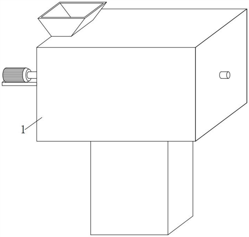

Image

  • Plastic fiber separator
  • Plastic fiber separator
  • Plastic fiber separator

Examples


Embodiment 1

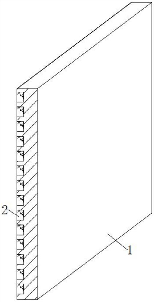
[0046] see Figure 1-4 , in the embodiment of the present invention, a plastic fiber separator, including

[0047] Shell 1, the inner position of the left outer surface of the shell 1 is arranged in an up-down and vertical direction, and several water-collecting components 2 that can collect sewage are embedded;

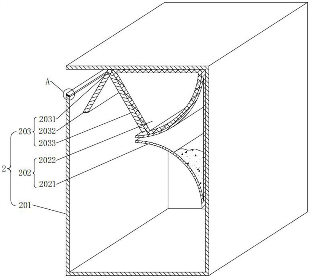
[0048] The water collection assembly 2, the water collection assembly 2 includes a water collection shell 201, a pretreatment assembly 202 that can preliminarily close the inlet before the capacity of the water collection shell 201 is saturated, and a pretreatment assembly 202 that can close the inlet of the water collection shell 203 to prevent the collected sewage from overflowing. Water sealing component 203;

[0049] The water collecting shells 201 are embedded in the inner position of the left outer surface of the casing 1 in the vertical and vertical directions, and are equally adjacent to each other;

[0050] A pretreatment assembly 202 is movably installed ...

Embodiment 2

[0058] see image 3 , Figure 5-6 , the difference between the embodiment of the present invention and the embodiment 1 is that the preprocessing component 202 includes:

[0059] The collection tank 2021, the collection tank 2021 is fixedly installed at the position between the right inner wall of the water collecting shell 201 and the top end. Right vertical shape, the material of the collection tank 2021 is copper;

[0060] The collection tank 2021 here has a shape that is hollow inside, concave at the upper left end, convex at the lower left end, and vertical at the right on a longitudinal section, and the material is made of copper. When the internal sewage water level line rises to the gap of the collection tank 2021, it means that the sewage is about to fill the water collecting shell 201. At this time, the sewage will enter the collection tank 2021 through the gap and come into contact with the quicklime powder in the collection tank 2021. A large amount of heat caus...

Embodiment 3

[0071] see image 3 and Figure 7 , the difference between the embodiment of the present invention and the embodiment 1 is that the water sealing component 203 includes:

[0072] As for the rotating shaft 2031, the left end of the top inner wall of the water collecting shell 201 is rotatably installed with the rotating shaft 2031 in the front-rear horizontal direction.

[0073] In the embodiment of the present invention, the water sealing component 203 further includes:

[0074] Left plate 2032, the left plate 2032 is fixedly installed around the lower left outer surface of the rotating shaft 2031, the length of the left plate 2032 is equal to the distance between the rotating shaft 2031 and the magnetic plate 2011, the left plate 2032 has different magnetism from the magnetic plate 2011, The angle between the plate 2032 and the vertical plane is 30° under normal conditions;

[0075] The length of the left plate 2032 here is equal to the distance between the rotating shaft ...


PUM


Abstract

The invention provides a plastic fiber separator which comprises a shell, and a plurality of water collecting assemblies capable of collecting sewage are embedded in the inner position of the outer surface of the left side of the shell in the up-down vertical direction in an equally adjacent manner; the water collecting assembly comprises a water collecting shell, a pretreatment assembly capable of pre-sealing an inlet before the inner capacity of the water collecting shell is saturated, and a water sealing assembly capable of sealing the inlet of the water collecting shell to prevent collected sewage from overflowing; the water collecting shells are embedded in the inner position of the outer surface of the left side of the shell in the up-down vertical direction in an equally-adjacent mode. And a pretreatment assembly is movably mounted between the right lower end and the right top end of the water collecting shell. According to the plastic fiber separator, the water collecting function can be achieved outside the left side of the shell, in the process of water spraying separation of plastic fibers in the shell, even if part of sewage is thrown out through the feeding port and flows out of the left side of the shell, the sewage can be collected in time, the sewage is prevented from overflowing to the motor, and the plastic fibers in the shell are separated. And the normal separation effect of the plastic fibers is ensured.

Description

technical field [0001] The present invention relates to the technical field of solid waste treatment equipment, and more particularly, to a plastic fiber separator. Background technique [0002] At present, the amount of waste paper in various countries is increasing year by year. At present, the annual amount of waste paper in my country is about 28 million tons, the consumption of waste paper pulp is about 62 million tons, and the generated papermaking waste is about 6 million tons. Calculated based on the fiber content of the waste residue at 2% , if not recycled, about 1.24 million tons will be lost every year; while papermaking waste mainly contains fibers and plastics and other substances, and fibers are attached to plastics, which not only affects plastic granulation, but also makes fibers difficult to recycle. [0003] In view of the above problems, regarding the technical problem of inconvenient separation of plastics and fibers, after a large number of searches, a p...

Claims


Application Information

Patent Timeline
IPC IPC(8): B09B3/30B08B17/02B09B101/85
CPCB09B3/00B08B17/025Y02W30/62
Inventor 黄艳
Owner 黄艳
Learn More