Objective lens unit, optical pickup and optical information device
A technology of optical pickup and objective lens, which is applied in the direction of beam guiding device, information storage, recording information storage, etc. It can solve problems such as difficulty in meeting specifications, and achieve the effects of suppressing resonance, reducing distance, and stabilizing control
- Summary
- Abstract
- Description
- Claims
- Application Information
AI Technical Summary
Problems solved by technology
Method used
Image
Examples
no. 1 Embodiment approach
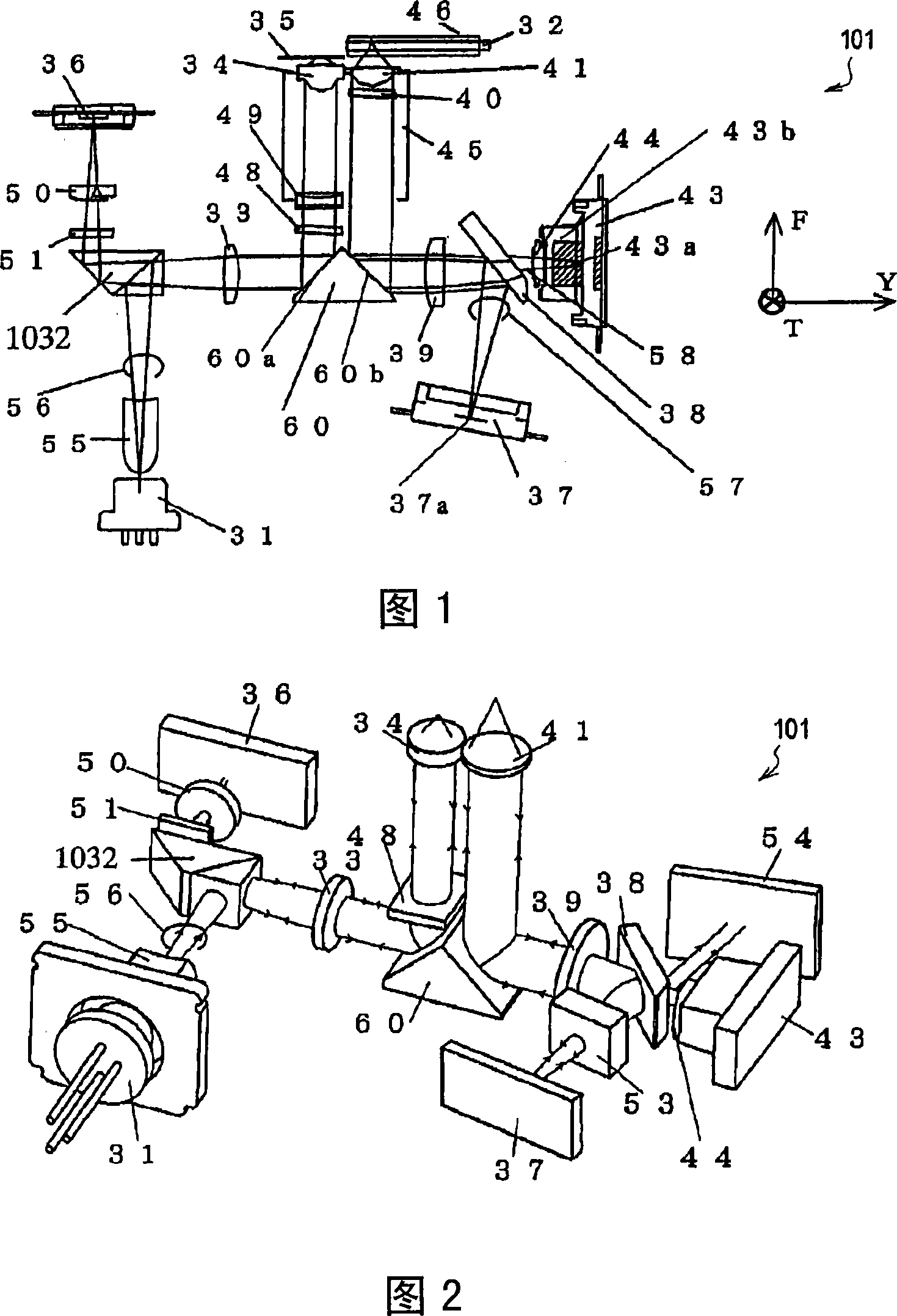
Next, a first embodiment of the optical pickup according to the present invention will be described. 1 and 2 are schematic side views and perspective views showing the optical pickup 101 .
[0066]
In FIG. 1, a direction T is a tracking direction, and a direction F is a focusing direction. In addition, the direction Y is a direction perpendicular to the tracking direction. The optical pickup 101 is arranged so that these directions coincide with the tracking direction, the focusing direction, and the direction perpendicular to the tracking direction of the optical information device (optical disk device). However, the direction Y and the direction T may be arranged to coincide with the tracking direction of the optical information device and the direction perpendicular thereto.
[0067]
The optical pickup 101 is capable of recording and reproducing at least one of the three optical discs 32, 35, 46 having different recording densities. The optical disks 32, 35, and 46 ar...
no. 2 Embodiment approach
In an optical pickup provided with a plurality of objective lenses, it is necessary to provide a plurality of through-holes serving as passages of light beams in the lens holder. In particular, in order to record and reproduce an optical disc with a high recording density, it is necessary to use an objective lens with a large numerical aperture. Therefore, the through hole also becomes larger. Since this type of lens holder has a large through hole, its rigidity is low and it tends to resonate at a predetermined frequency. In the optical pickup of the present embodiment, an objective lens driving device having a structure for suppressing deterioration of servo performance due to lens holder resonance is provided.
[0144]
12 and 13 are a perspective view and an exploded perspective view showing an objective lens driving device using the optical pickup of this embodiment. As in the first embodiment, arrows F, T, and Y indicate the focusing direction, the tracking direction, ...
no. 3 Embodiment approach
In this embodiment, an objective lens driving device having an appropriate structure for realizing the distance between the two objective lenses described in the second embodiment will be described.
[0170]
21 and 22 are a plan view and an exploded perspective view showing the objective lens driving device 103 according to this embodiment. The direction T, the direction Y, and the direction F shown in FIGS. 21 and 22 represent the tracking direction, the focusing direction, and the tangential direction of the optical disc, as in the second embodiment.
[0171]
The objective lens driving device 103 includes a movable body including an objective lens 301, an objective lens 302, a lens holder 303, focusing coils 304a to 304d, and tracking coils 305a and 3005b.
[0172]
The lens holder 303 is made of resin, and supports the objective lens 301 and the objective lens 302 . The objective lens 301 is used for recording and reproducing optical discs with low recording density su...
PUM
 Abstract
Description
Claims
Application Information
 - R&D
- Intellectual Property
- Life Sciences
- Materials
- Tech Scout
- Unparalleled Data Quality
- Higher Quality Content
- 60% Fewer Hallucinations
Browse by: Latest US Patents, China's latest patents, Technical Efficacy Thesaurus, Application Domain, Technology Topic, Popular Technical Reports.
© 2025 PatSnap. All rights reserved.Legal|Privacy policy|Modern Slavery Act Transparency Statement|Sitemap|About US| Contact US: help@patsnap.com


