Light source and method for producing light modifiable in colour and/or luminosity

A light source and color technology, applied in electroluminescence light sources, chemical instruments and methods, light sources, etc., can solve problems such as changes, and achieve the effect of achieving saturation characteristics

Active Publication Date: 2008-08-13
SIGNIFY HLDG BV
View PDF0 Cites 32 Cited by
  • Summary
  • Abstract
  • Description
  • Claims
  • Application Information

AI Technical Summary

Problems solved by technology

A disadvantage of known light sources is that the color of the light leaving the light source changes as the brightne

Method used


Image

  • Light source and method for producing light modifiable in colour and/or luminosity
  • Light source and method for producing light modifiable in colour and/or luminosity
  • Light source and method for producing light modifiable in colour and/or luminosity

Examples


Embodiment Construction

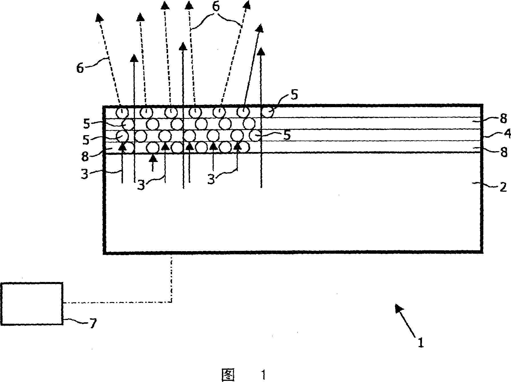
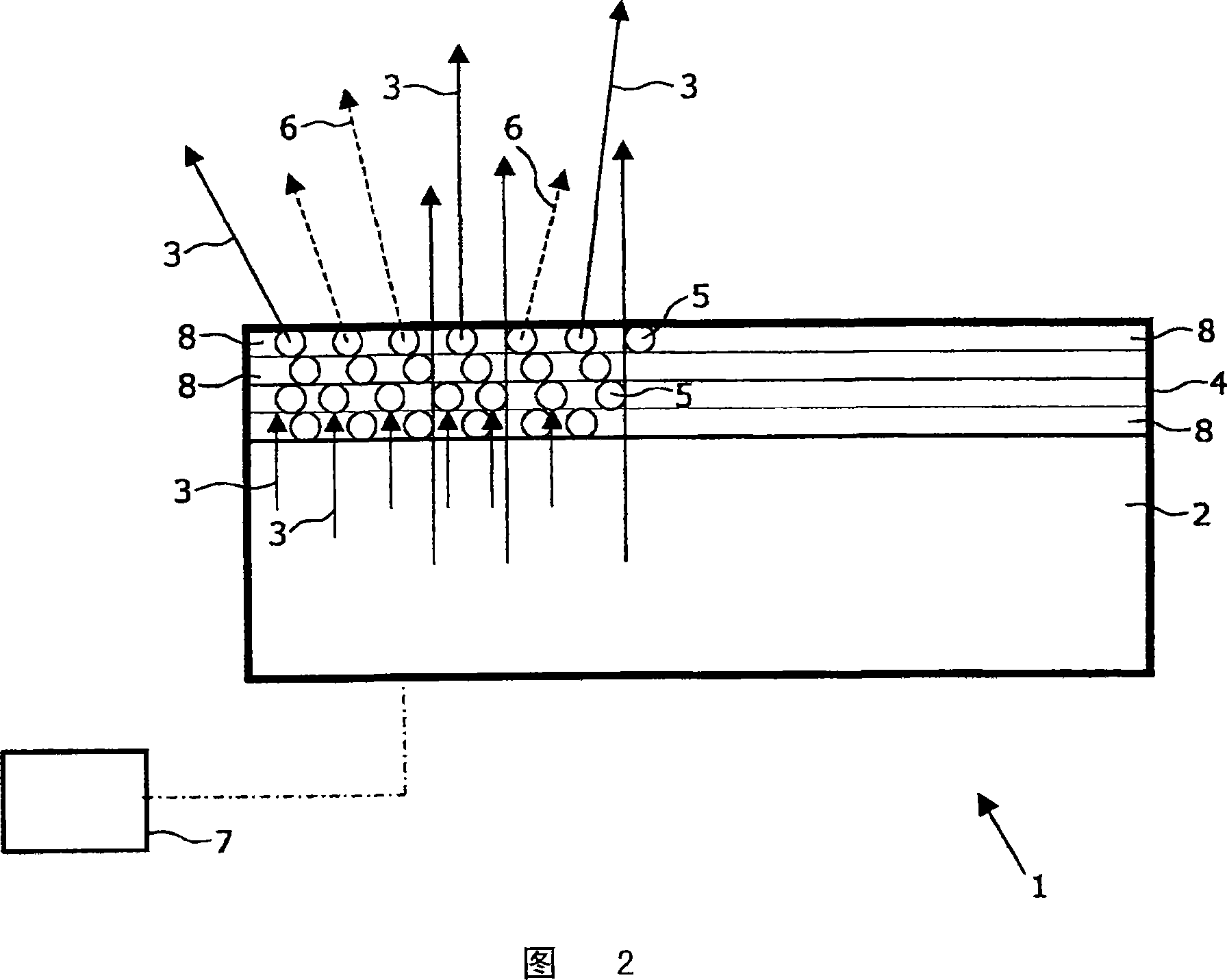
[0031] FIG. 1 shows a light source 1 comprising a single light emitting diode 2 connected to a switching device 7 . A layer 4 with a phosphor 5 is arranged on top of the diode 2 . If the diode 2 is driven with a pulse-shaped current, the diode 2 emits visible light 3 , which is radiated in the direction of the layer 4 . In this embodiment, visible light 3 (primary radiation) is blue light with a first peak wavelength at 455 nanometers. Simultaneously with diode 2 emitting primary blue radiation 3 , phosphor 5 in embedded layer 4 is excited by photons of blue radiation 3 , whereby the blue light is converted into secondary radiation 6 . In the embodiment shown in Figures 1 and 2, the luminescent material 5 comprises a phosphor, which emits yellow light during conversion. In the depicted Figures 1 and 2, CaS:Eu is used as the phosphor material.

[0032] Upon increasing the pulse width modulated (PWM) excitation density, the phosphor 5 starts to saturate due to depletion of th...


PUM

PropertyMeasurementUnit
Densityaaaaaaaaaa

Abstract

The invention relates to a light source which produces light exiting the light source of variable color and brightness and which has at least one light-emitting diode for emitting primary radiation and which comprises a layer connected to said diode, wherein said layer comprises at least A luminescent material used to convert primary radiation into secondary radiation.

Description

technical field [0001] The invention relates to a light source with at least one light-emitting diode emitting primary radiation, said light source comprising a layer connected to said diode, said layer comprising at least one luminescent material for converting primary radiation into secondary radiation. Background technique [0002] It is well known that light emitting diodes (LEDs), such as phosphor converted light emitting diodes, produce light with a high color rendering index. However, the color temperature of the light of each individual phosphor-converted light-emitting diode is fixed over a wide color temperature range. An obvious disadvantage is that by increasing the excitation density to the phosphor, the phosphor starts to saturate due to ground-state depletion or thermal quenching of luminescence. During this saturation process, the layer with luminescent material emits more and more primary radiation. The color of the light leaving the light source, which is...

Claims


Application Information

Patent Timeline
IPC IPC(8): H01L33/00H05B33/00H01L33/50H05B44/00
CPCH05B33/0818H05B33/14C09K11/7792H01L33/502C09K11/7718C09K11/7731C09K11/7777C09K11/586C09K11/584C09K11/7734C09K11/7789C09K11/0883C09K11/7478C09K11/7739C09K11/7774C09K11/7794H01L2924/0002H05B33/0863C09K11/778H05B45/20H01L2924/00H05B33/00
Inventor C·R·朗达
Owner SIGNIFY HLDG BV
Why Eureka
Try Eureka