
Concrete distributing valve and concrete pumping mechanism

A concrete pump and distribution valve technology, applied in the direction of conveyors, components of pumping devices for elastic fluids, pumps, etc., can solve the problems of affecting the suction of the conveying cylinder and occupying the volume of the hopper, and achieve better suction performance. , the use of increased volume, easy to clean the effect

Inactive Publication Date: 2008-08-20
SANY AUTOMOBILE MFG CO LTD
View PDF0 Cites 29 Cited by
  • Summary
  • Abstract
  • Description
  • Claims
  • Application Information

AI Technical Summary

Problems solved by technology

The advantage of the S valve is that the high pressure of the system mainly acts on the inner wall of the circular pipe. When working, the entire pipe wall is evenly tensioned and can withstand a large pressure. The working pressure can reach 16MPa or even greater. However, due to the S pipe of the S valve In the hopper, it occupies a certain volume of the hopper, and it will affect the suction of the delivery cylinder

Method used


Image

  • Concrete distributing valve and concrete pumping mechanism
  • Concrete distributing valve and concrete pumping mechanism
  • Concrete distributing valve and concrete pumping mechanism

Examples


Embodiment Construction

[0029] The invention provides a concrete distributing valve, which not only has good material suction performance but also can meet the pumping requirements of relatively high pressure.

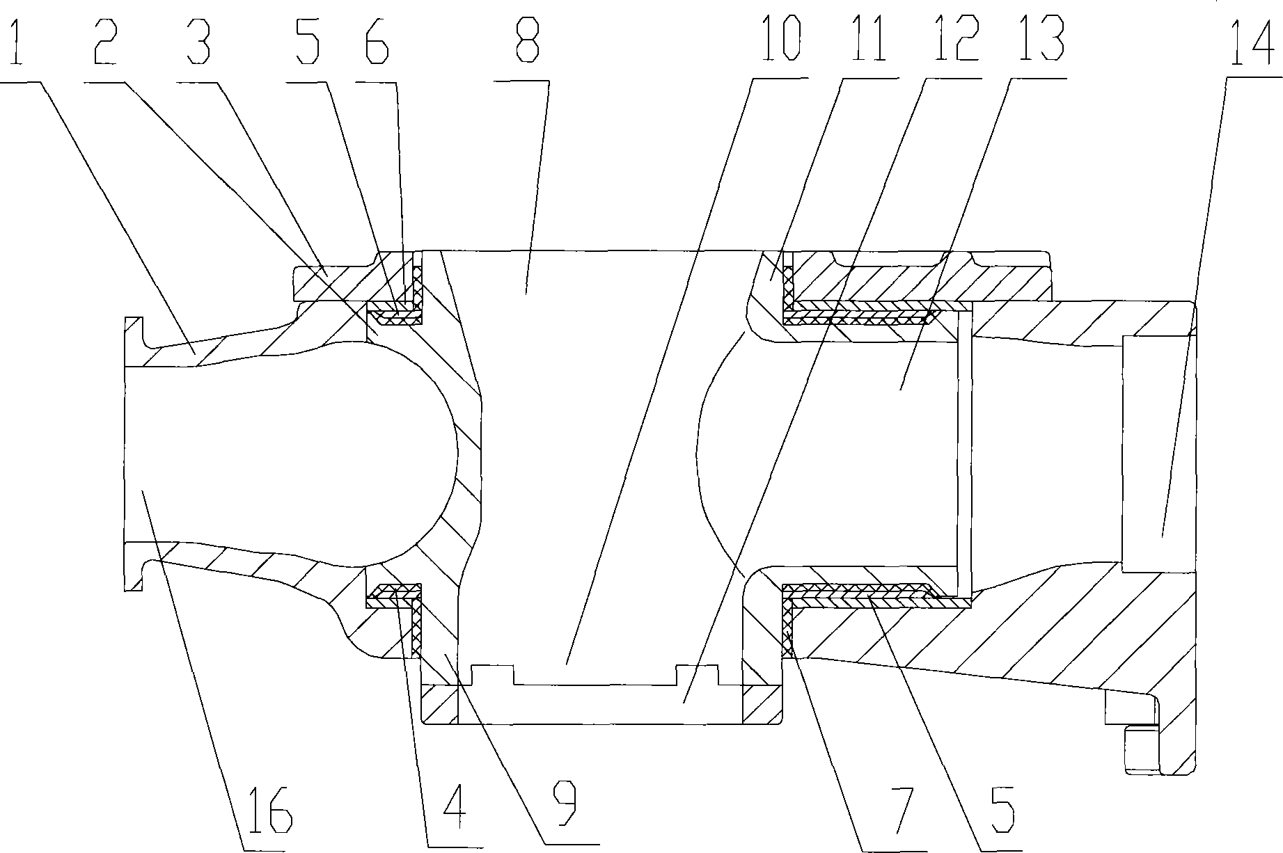
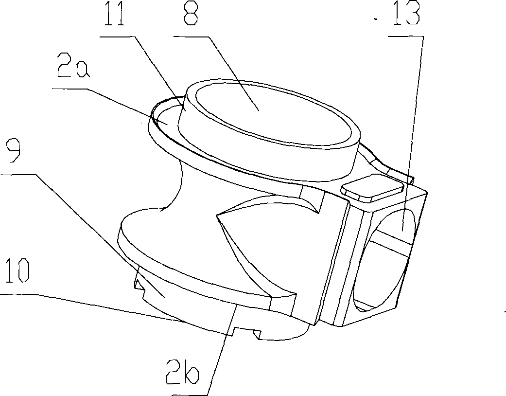
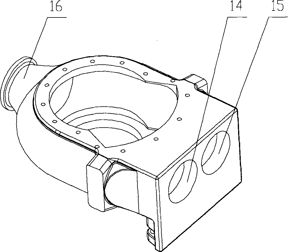
[0030] see Figure 1 to Figure 3 , figure 1 It is a structural schematic diagram of the concrete distribution valve described in the embodiment of the present invention; figure 2 It is a side view of the spool described in the embodiment of the present invention; image 3 It is an axonometric view of the valve body described in the embodiment of the present invention.

[0031] The concrete distribution valve in the embodiment of the present invention includes a valve body 1 and a valve core 2 located in the valve body 1 . The valve body 1 has a material outlet 16 , a first material intake 14 and a second material intake 15 .

[0032] The spool 2 has a side opening 13 and a concrete pump hopper 17 (see Figure 6 ) connected feed port 8. The side opening 13 may be perpendicular to the fe...


PUM


Abstract

The invention discloses a concrete distribution valve, comprising a valve body and a valve core which is arranged in the valve body. The valve body is provided with a material outlet, a first material suction port and a second material suction port. The valve core is provided with a side opening and a material inlet which is communicated with a concrete material hopper. The valve core can rotate for a certain angle correspondingly to the valve body. When the valve core rotates to a left limit position correspondingly to the valve body, the side opening is communicated with the first material suction port. When the valve core rotates to a right limit position correspondingly to the valve body, the side opening is communicated with the second material suction port. A passage which is communicated with the first material suction port, the second material suction port and the material outlet is arranged between the valve core and the valve body. The invention provides a concrete distribution valve and a concrete pumping mechanism, which has good material suction performance and can meet the pumping requirement.

Description

technical field [0001] The invention relates to a concrete distribution valve and a concrete pumping mechanism, in particular to a concrete distribution valve used for a concrete delivery pump and a concrete pumping mechanism using the concrete distribution valve. Background technique [0002] At present, in the domestic and foreign markets, there are two main types of concrete distribution valves: gate valve and S valve. [0003] The gate valve is through the up and down movement of the two gates in the distribution valve, so that the delivery cylinder is connected or disconnected sequentially through the distribution valve, the feed port of the hopper and the discharge port of the Y-shaped pipe, so as to realize the suction of concrete. and pumping process. The advantage of the gate valve is that the suction port is located at the bottom of the hopper, and there are only stirring blades in the hopper, so the volume ratio of the hopper is high, and the material suction per...

Claims


Application Information

Patent Timeline
Patent Type & Authority Applications(China)
IPC IPC(8): F16K11/08F04B15/02F04B53/10B65G53/46
Inventor 梁永交易小刚易秀明李良荣杨新华李永维
Owner SANY AUTOMOBILE MFG CO LTD
Learn More