
Finned heat exchanger

A finned heat exchanger and fin technology, which is applied in heat exchange equipment, lighting and heating equipment, tubular elements, etc., can solve the problems of insignificant improvement of gas side heat exchange performance, increase flow resistance, etc., and save energy. The effect of producing consumables, increasing flow resistance, and reducing flow resistance

Inactive Publication Date: 2008-08-20
XI AN JIAOTONG UNIV
View PDF1 Cites 23 Cited by
  • Summary
  • Abstract
  • Description
  • Claims
  • Application Information

AI Technical Summary

Problems solved by technology

However, these traditional measures to enhance heat transfer have the following problems: (1) the effect of improving the heat transfer performance of the gas side is not significant; (2) while improving the heat transfer coefficient of the gas side, the flow resistance is also greatly increased, Often the increase in flow resistance is higher than (or even several times) the increase in heat transfer capacity

Method used


Image

  • Finned heat exchanger
  • Finned heat exchanger
  • Finned heat exchanger

Examples


Embodiment 1

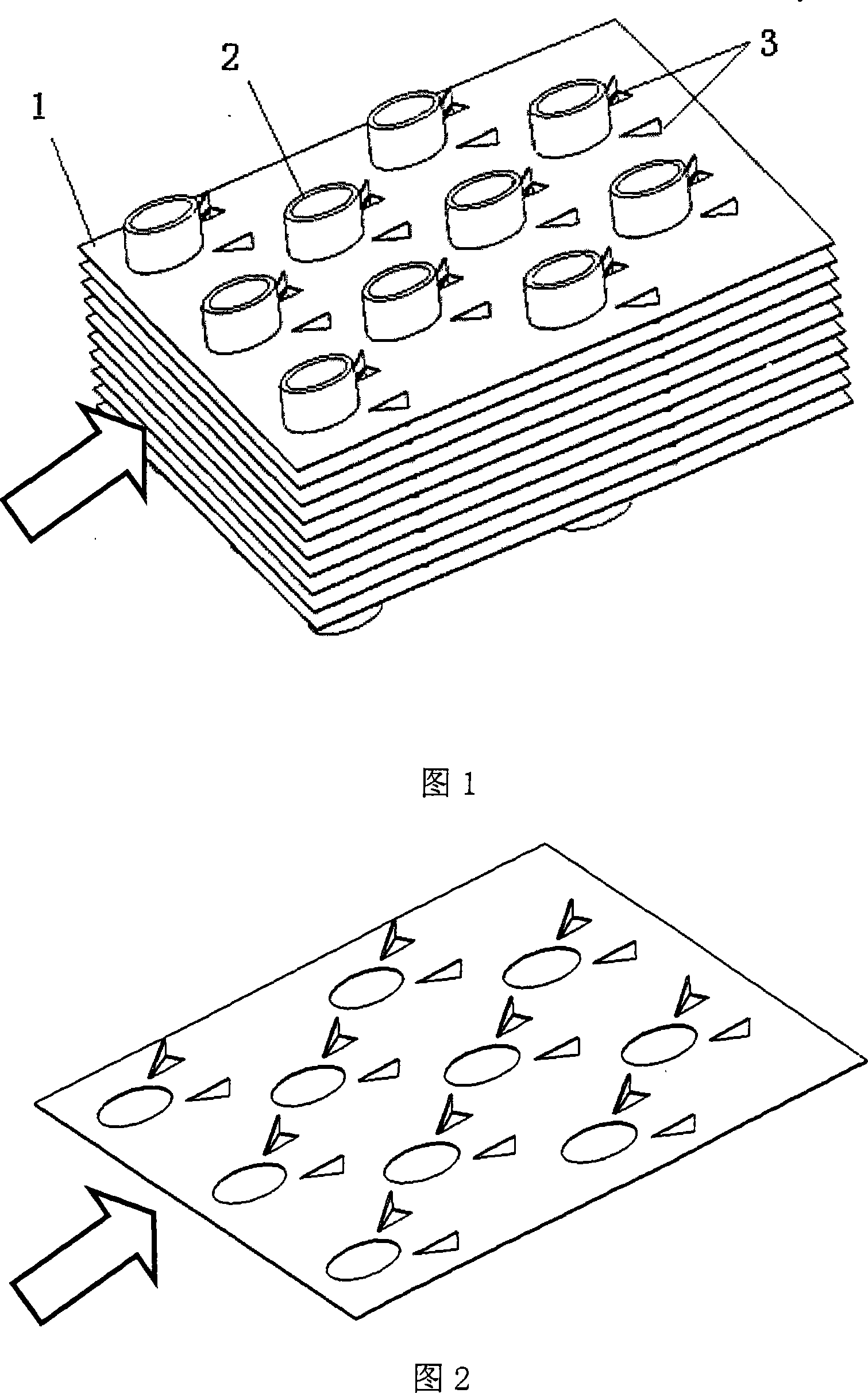
[0023] Referring to Figure 1, in this embodiment, the fin 1 is a flat continuous fin, and the longitudinal vortex generator is a triangular winglet 6, which is pasted on the fin 1. After the air side fluid enters the heat exchanger, it meets the ellipse The longitudinal vortex generator 3 around the heat exchange tube 2 produces a strong tangential rotation, forming a longitudinal vortex that develops along the main flow direction. Under the strong rotational entrainment of the longitudinal vortex, it thins or even destroys the boundary layer generated by the air side fluid along the flow channel, and introduces high-velocity fluid into the wake area, thereby inhibiting the development of the wake area and enhancing the wake area and the mainstream The longitudinal vortex produces strong rotation in the tangential direction, and the fluid in the inner edge area of ​​the entrained gas side flow channel enters the main flow area to aggravate the mixing between the gas side fluids an...

Embodiment 2

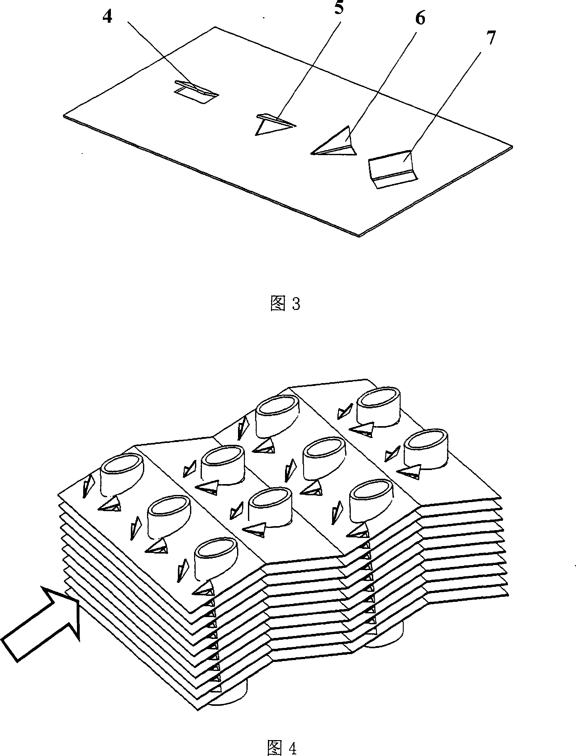
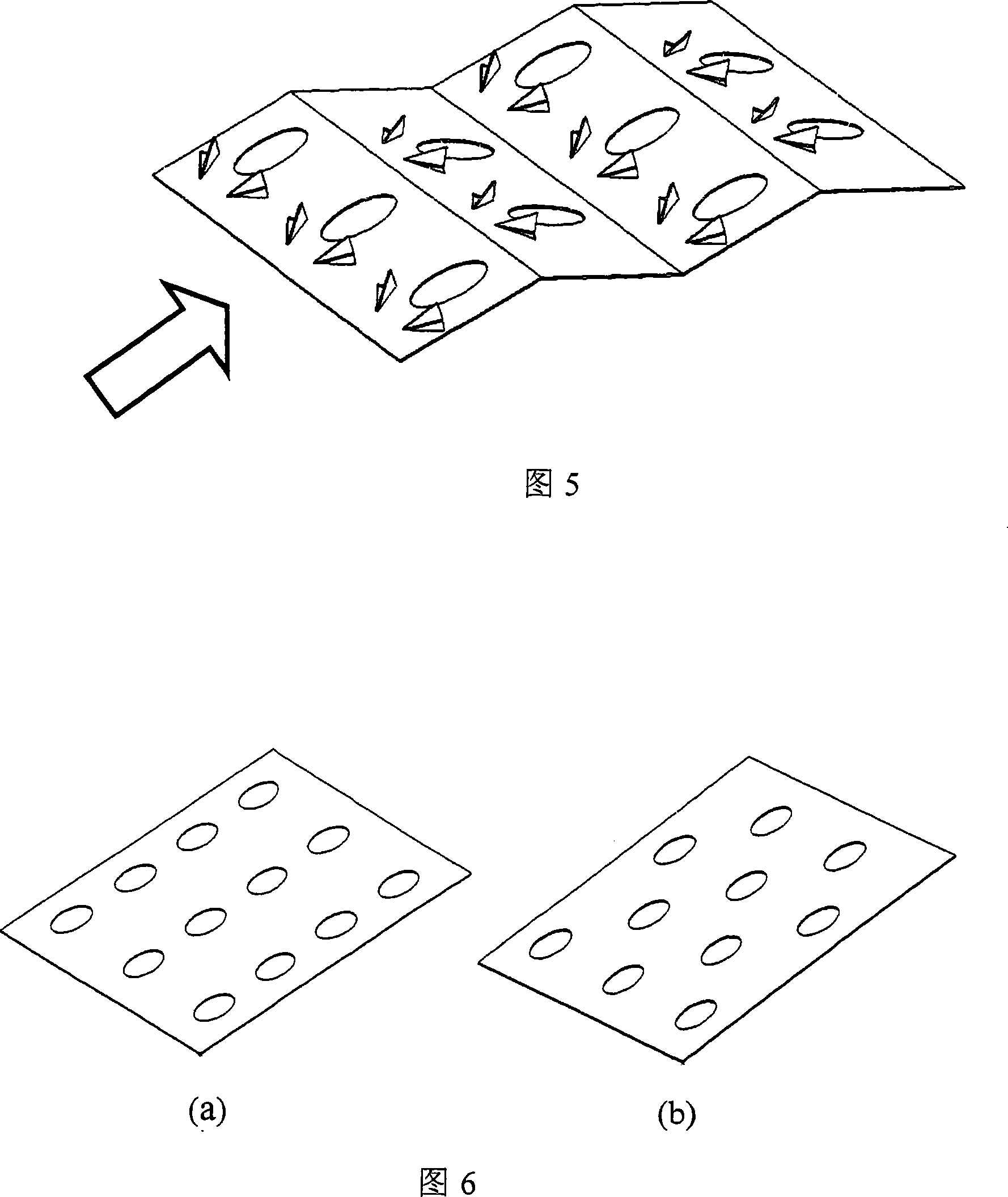
[0025] In this embodiment, compared with Embodiment 1, the difference lies in that the fin plate 1 uses corrugated continuous fins, see FIG. 3 and FIG. 4. Because the corrugated continuous fin 5 is used, in addition to the heat transfer enhancement effect described in Example 1, the disturbance of the air side fluid perpendicular to the main flow direction is further enhanced, so that the growth cycle of the fluid flow boundary layer and the thermal boundary layer Due to the fracture, the flow and heat transfer boundary layer has been further disturbed and destroyed, so that the heat transfer coefficient of the air side has been further improved. In a limited space, the use of corrugated continuous fins can get a larger heat exchange area. Therefore, the use of corrugated continuous fins can increase the heat exchange area and increase the heat exchange coefficient at the same time, so that the overall performance of the heat exchanger is further improved.

[0026] The actual appl...


PUM


Abstract

The invention relates to the field of heat exchangers, in particular to a fin-typed heat exchanger with high efficiency and low resistance, comprising a fin row which consists of fins and a heat exchange pipe which vertically passes through the fin row. The fin-typed heat exchanger is characterized in that the section of the heat exchange pipe is an ellipse shape; the fin is provided with a longitudinal vortex generator. The fin-typed heat exchanger can greatly improve the whole heat exchange performance of the heat exchanger but increases the flow resistance to small extent at the same time, and is mainly applied to gas-liquid heat exchange or gas-phase variable heat exchange.

Description

Technical field [0001] The invention relates to the field of heat exchangers, in particular to a fin type heat exchanger with high efficiency and low resistance. Background technique [0002] Finned heat exchangers are mostly used for gas-liquid heat exchange or gas-phase heat transfer, and have a wide range of applications in air conditioning, electronic device cooling, heating, ventilation, refrigeration, aerospace and other fields. With the increase of social environmental protection awareness and the pressure of energy shortage, higher and higher requirements are put forward for the energy efficiency of heat exchangers. [0003] Due to the thermophysical properties of the gas itself, in a finned heat exchanger, the heat transfer coefficient on the gas side is very low compared to the heat transfer coefficient on the tube side, generally 20W / m 2 ·K~100W / m 2 ·K (The heat transfer coefficient inside the tube is generally 1000W / m 2 ·K~15000W / m 2 ·K ). The thermal resistance on th...

Claims


Application Information

Patent Timeline
Patent Type & Authority Applications(China)
IPC IPC(8): F28F1/30
Inventor 何雅玲楚攀雷勇刚陶文铨高凡
Owner XI AN JIAOTONG UNIV
Learn More