Multi-screen real-time signal processing method and system
A real-time signal and signal processing unit technology, applied in cathode ray tube indicators, instruments, static indicators, etc., can solve the problem of high cost, achieve the effect of simple wiring, ensure smoothness, and reduce transmission delay
- Summary
- Abstract
- Description
- Claims
- Application Information
AI Technical Summary
Problems solved by technology
Method used
Image
Examples
Embodiment 1
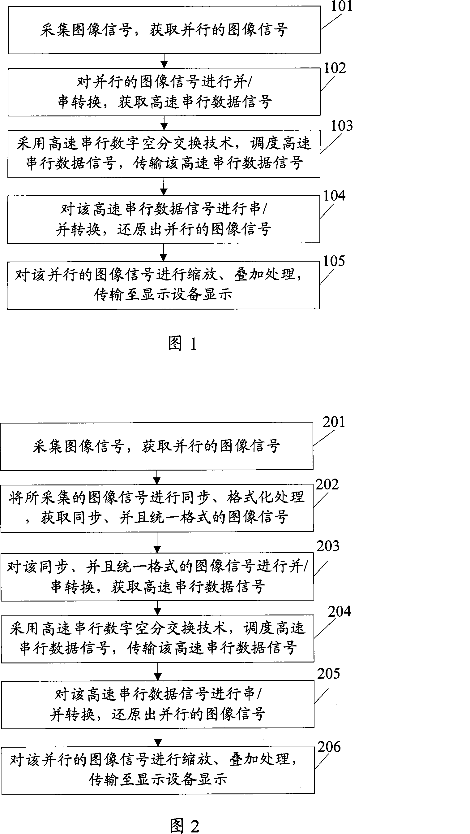
[0041] FIG. 1 is a schematic flowchart of a method for multi-screen real-time signal processing provided in this embodiment. As shown in the figure, the method includes:
[0042] Step 101: collect image signals, and acquire parallel image signals.
[0043] The signal acquisition unit can acquire parallel image signals (such as video signals) by using various image signal acquisition technologies in the prior art according to actual needs. For example: sampling an analog image signal, obtaining a digital image signal (A / D conversion), decoding, deinterlacing, etc.
[0044] Step 102: Parallel / serial conversion is performed on parallel image signals to obtain high-speed serial data signals.
[0045] Converts parallel image signals to high-speed serial data signals. Its specific conversion technical scheme can be carried out by adopting various technical schemes of the prior art.
[0046] After the parallel / serial conversion, the parallel / serial conversion subunit inputs the ob...
Embodiment 2
[0061] FIG. 2 is a schematic flowchart of another method for multi-screen real-time signal processing provided by an embodiment of the present invention. As shown in the figure, the method includes:
[0062] Step 201: collect image signals, and acquire parallel image signals.
[0063] It is the same as step 101 in Embodiment 1.
[0064] Step 202: Synchronize and format the collected image signals to obtain synchronized image signals with a unified format.
[0065] Compared with the technical solution of the embodiment, the technical solution of this embodiment is that this step is added, that is, between the parallel / serial conversion and the acquisition of the high-speed serial data signal, the image signal is synchronized and formatted to obtain an image signal of a unified format.
[0066] The advantage of adding this step is that all input signals are eventually synchronized to the same synchronous signal, which can meet special applications such as TV stations, and event...
Embodiment 3
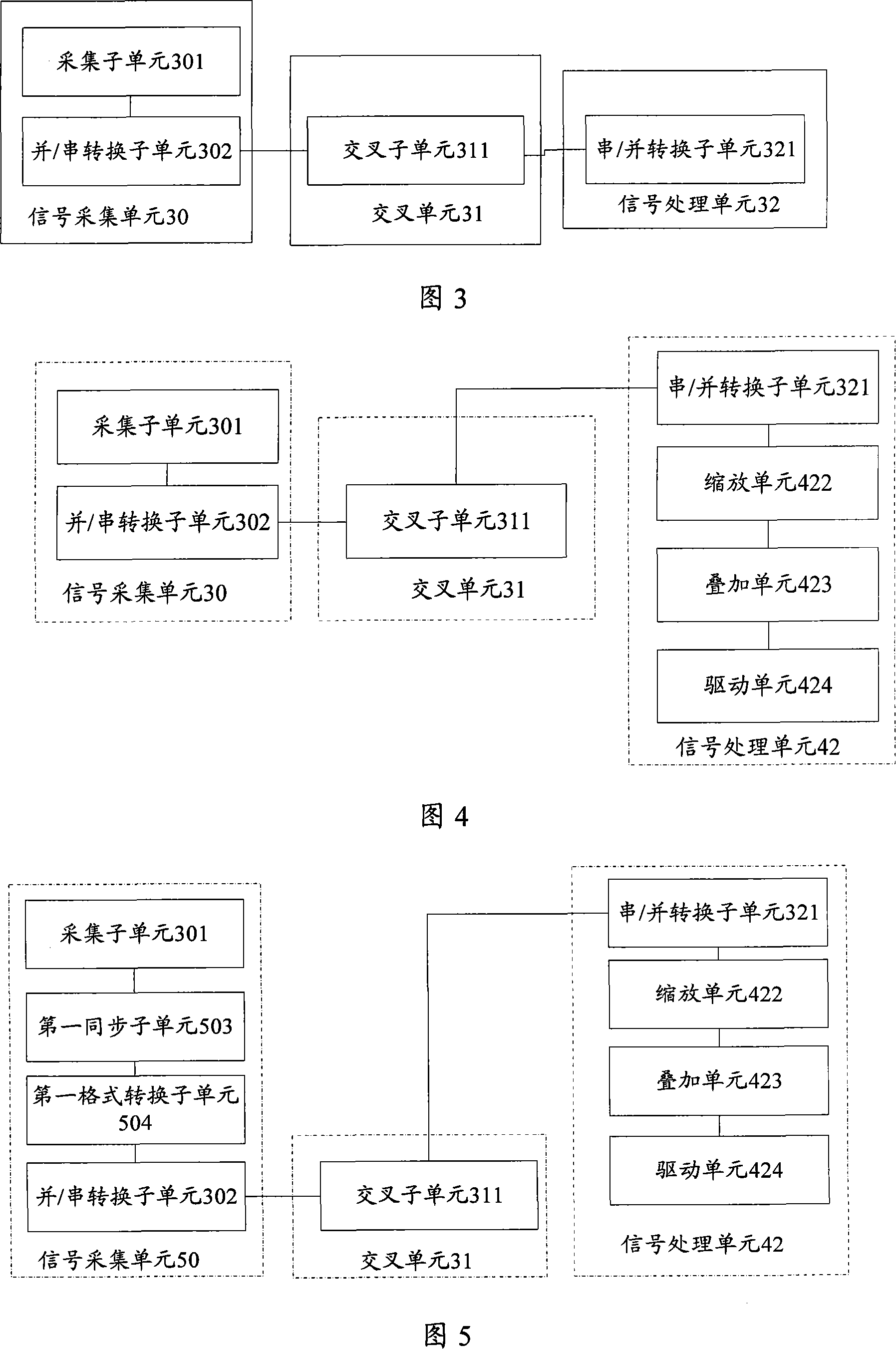
[0076] FIG. 3 is a multi-screen real-time signal processing system provided by this embodiment, and the system includes: a signal acquisition unit 30 , a crossover unit 31 , and a signal processing unit 32 .
[0077] The signal acquisition unit 30 includes:
[0078] The acquisition subunit 301 is configured to acquire image signals and acquire parallel image signals. For the principle, refer to step 101 in the embodiment.
[0079] The parallel / serial conversion subunit 302 is used to perform parallel / serial conversion on the parallel image signal acquired by the acquisition subunit 301, convert the parallel image signal into a high-speed serial data signal, and transmit the high-speed serial data signal to cross unit 31. For its principle, refer to step 102 in Embodiment 1.
[0080] Crossover unit 31 includes:
[0081] The cross-connect subunit 311 is configured to use high-speed serial digital space division switching technology to schedule the high-speed serial data sign...
PUM
 Abstract
Description
Claims
Application Information
 - R&D
- Intellectual Property
- Life Sciences
- Materials
- Tech Scout
- Unparalleled Data Quality
- Higher Quality Content
- 60% Fewer Hallucinations
Browse by: Latest US Patents, China's latest patents, Technical Efficacy Thesaurus, Application Domain, Technology Topic, Popular Technical Reports.
© 2025 PatSnap. All rights reserved.Legal|Privacy policy|Modern Slavery Act Transparency Statement|Sitemap|About US| Contact US: help@patsnap.com


