
Vehicle xenon headlight fixer

A technology of xenon headlights and ballasts is applied in the field of electronics to achieve the effect of reducing manufacturing and installation costs and saving installation space

Inactive Publication Date: 2008-08-20
殷强
View PDF0 Cites 1 Cited by
  • Summary
  • Abstract
  • Description
  • Claims
  • Application Information

AI Technical Summary

Problems solved by technology

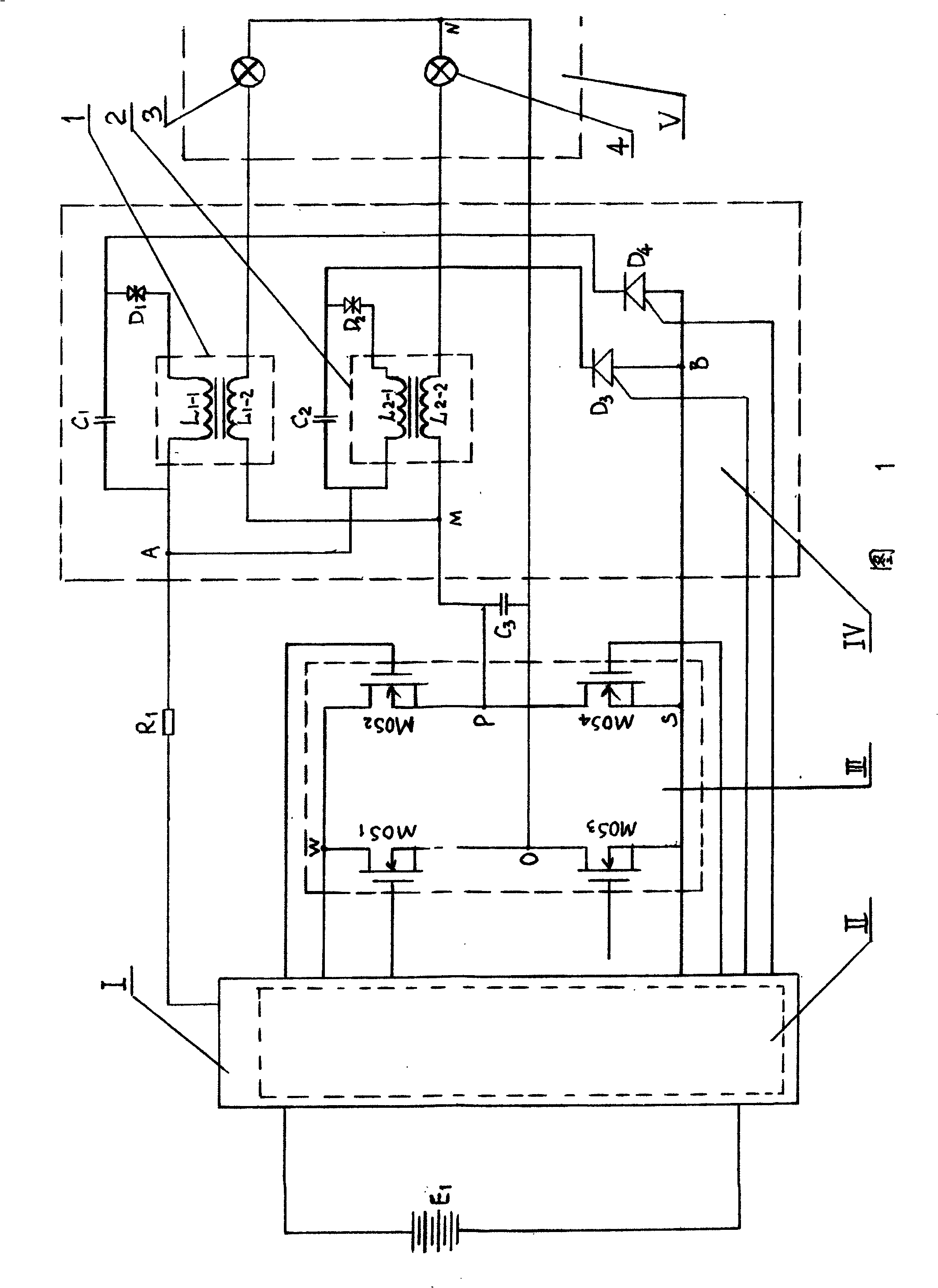
[0003] The technical problem to be solved by the present invention is to provide a new type of automotive xenon headlight ballast to solve the problem of alternately lighting two xenon bulbs with one ballast

Method used


Image

  • Vehicle xenon headlight fixer

Examples


Embodiment Construction

[0013] As shown in Fig. 1, this embodiment includes a boost circuit I and a control circuit II, both of which are of general structure. The boost circuit I converts the car battery E 1 The DC low voltage is raised to the high voltage DC for driving the xenon lamp, and the voltage is applied between the first node W and the second node S of the double-bridge inverter circuit III.

[0014] The double bridge inverter circuit III is composed of the first field effect tube MOS 1 and a third FET MOS 3 Connected in series, the connection node is the eighth node O point, this series circuit forms the first bridge arm, and the second field effect transistor MOS 2 and the fourth FET MOS 4 connected in series, the connection node is point P with the fourth node, and this series circuit forms the second bridge arm. The first bridge arm and the second bridge arm are connected in parallel to form a double-bridge inverter circuit III, and the parallel connection intersects the first node...


PUM


Abstract

The invention provides an automotive xenon headlamp stabilizer. Starting ignition circuit (IV) has first FBT (1) and second FBT (2), fourth point (P) of double-bridge inverter circuit (III) simultaneous connects with secondary side coils of first FBT (1) and second FBT (2) in starting ignition circuit. Two FBT is installed in the stabilizer, can start two xenon bulbs respectively and make the bulbs working alternately. The stabilizer function is played at maximum efficiency, manufacturing installing cost is reduced and installing space is saved.

Description

technical field [0001] The invention relates to an automobile xenon headlight stabilizer, which belongs to the field of electronic technology. Background technique [0002] Previous ballasts can only drive a xenon bulb to emit light. But there are many occasions that need to have two xenon bulbs to emit light alternately. In the past, this situation required two ballasts with two xenon bulbs, which not only increased the cost but also increased the installation space. Contents of the invention [0003] The technical problem to be solved by the present invention is to provide a new type of automobile xenon headlight ballast, which solves the problem of alternately lighting two xenon bulbs with one ballast. [0004] The present invention adopts the following technical solutions. [0005] A kind of automotive xenon headlight stabilizer, including a boost circuit, a control circuit, a double-bridge inverter circuit and a starting ignition circuit; the first node and the sec...

Claims


Application Information

Patent Timeline
Patent Type & Authority Applications(China)
IPC IPC(8): H05B41/24H05B41/36
CPCY02B20/204Y02B20/00
Inventor 殷强
Owner 殷强
Learn More