Supercharge Your Innovation With Domain-Expert AI Agents!

Method and system for performing an interfacial reaction in a microfluidic device

A technology for performing interface and reaction, applied in the preparation of microspheres, microcapsule preparations, etc., can solve the problems of polymer debris blocking in microfluidic devices

Inactive Publication Date: 2008-08-20
CORNELL RES FOUNDATION INC
View PDF2 Cites 2 Cited by
  • Summary
  • Abstract
  • Description
  • Claims
  • Application Information

AI Technical Summary

Problems solved by technology

However, these methods require expensive monomer synthesis or specialized techniques, and the resulting microfluidic devices are prone to clogging with polymeric debris

Method used


Image

  • Method and system for performing an interfacial reaction in a microfluidic device
  • Method and system for performing an interfacial reaction in a microfluidic device
  • Method and system for performing an interfacial reaction in a microfluidic device

Examples


Embodiment Construction

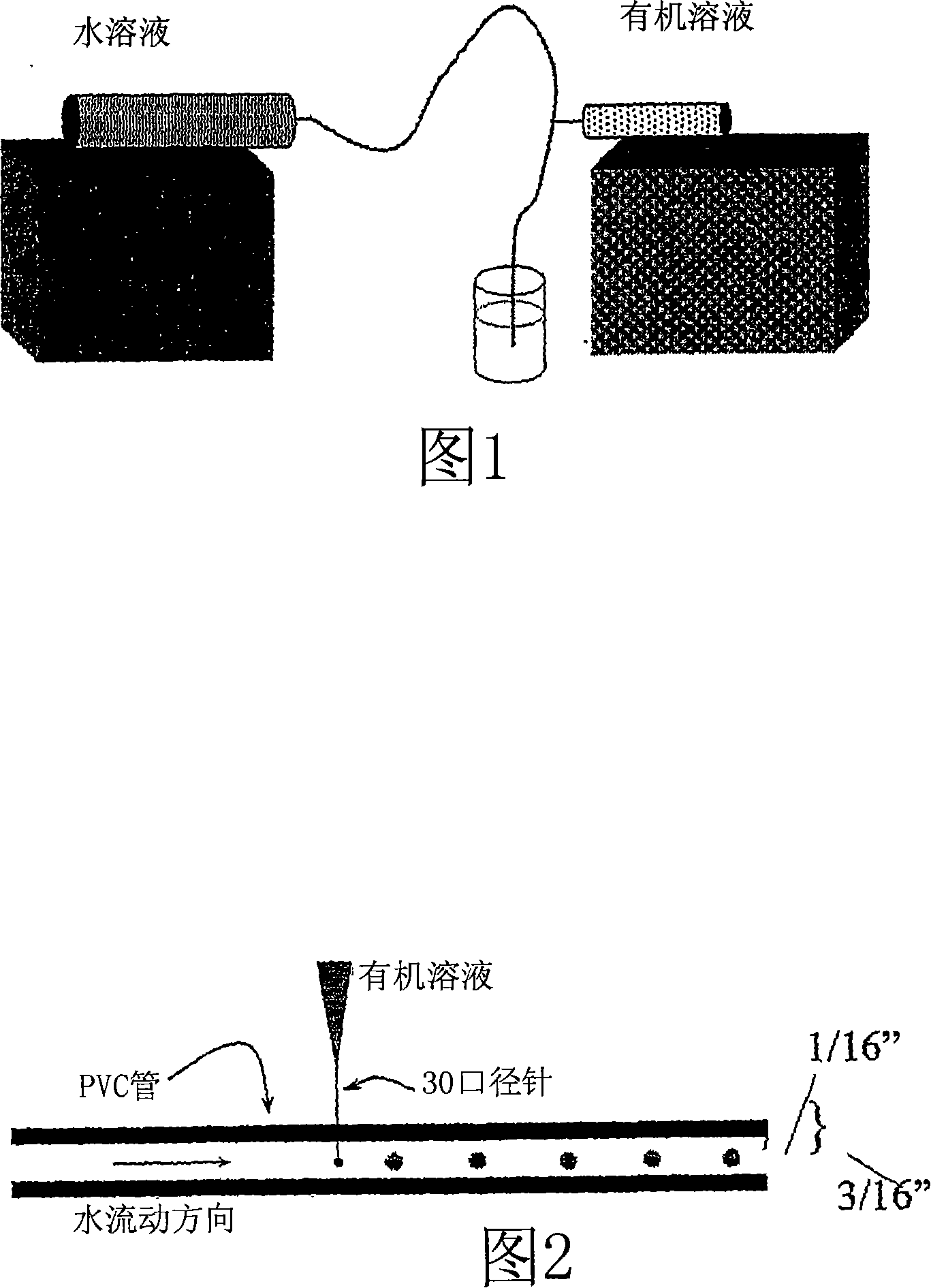
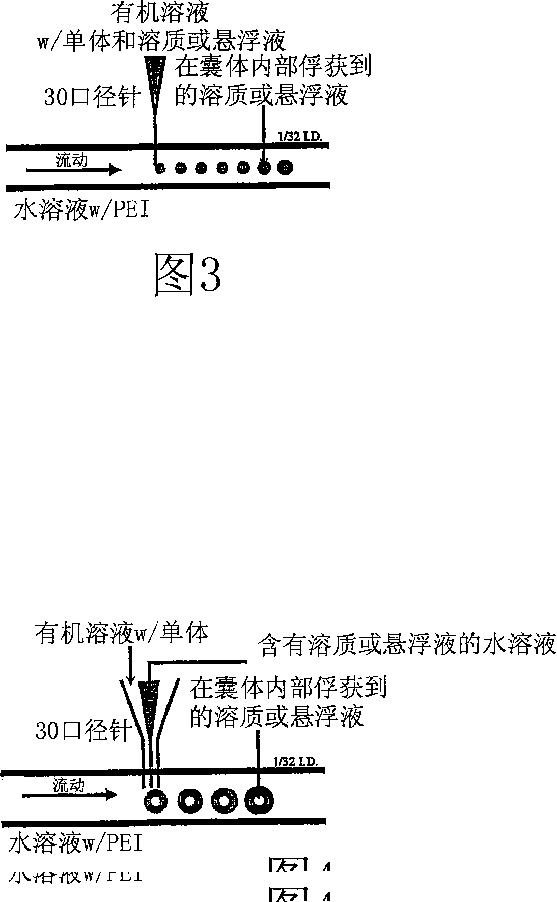
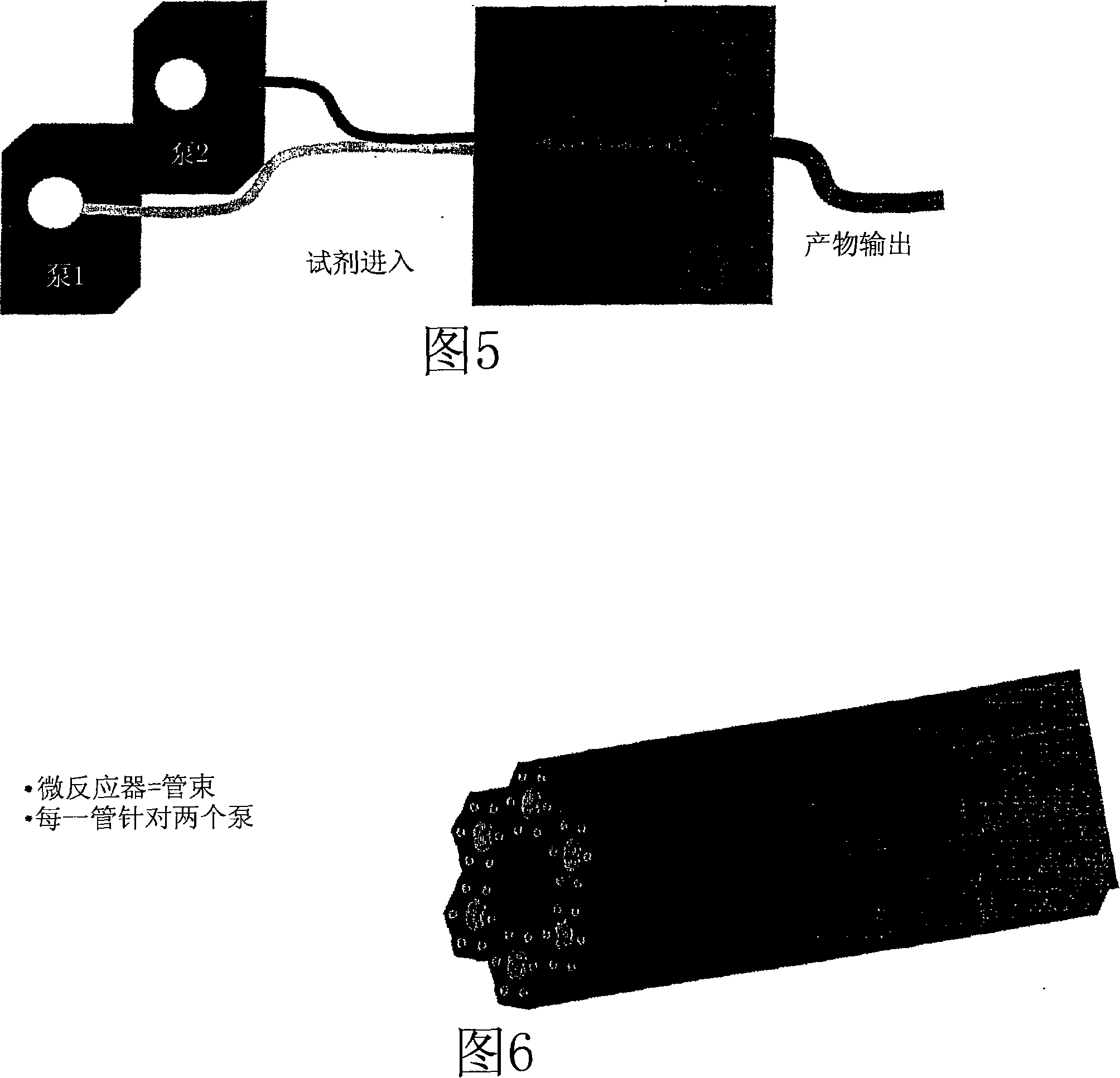
[0029] A simple microfluidic system for performing interfacial reactions may include at least one pump in fluid communication with a tube. Preferably, the tube is substantially cylindrical. A first fluid is injected into the tube such that its flow is stratified and continuous. Preferably, the Reynolds number of the first fluid is <2500, and more preferably <1000. A second fluid is injected into the tube, into the flow or flow of the first fluid. Preferably, the second fluid is injected in discrete quantities. In some embodiments, the first fluid is first injected with a continuous stratified flow such that the second fluid is injected directly into the flow of the first fluid. In other embodiments, discrete amounts of the second fluid are first introduced into the channel, and then the first fluid is injected such that it forms a substantially laminar fluid flow region around the discrete amounts of the second fluid. After the two fluids come into contact, a reaction occu...


PUM


Abstract

A microfluidic system for performing interfacial reactions can comprise at least one pump in fluid communication with a tube. A first fluid is injected into the tube so that its flow is laminar and continuous. A second fluid is injected in discrete amounts into the tube into the stream or flow of the first fluid. In other embodiments, discrete amounts of the second fluid are introduced into the channel first, then the first fluid is injected so that it creates a region of substantially laminar fluid flow around the discrete amounts of the second fluid. After the two fluids are in contact, a reaction occurs. The system can be configured so that the second fluid solidifies to form a capsule around the first fluid or vice versa. Other interfacial reactions also can be accomplished using the disclosed microfluidic systems and methods.

Description

[0001] Cross References to Related Applications [0002] The present application claims the benefit of US Provisional Application No. 60 / 683,656, filed May 23, 2005, the entire disclosure of which is incorporated herein for any purpose. [0003] Statement Regarding Federally Sponsored Research or Development [0004] This invention was made with Government support from the Army / Army Research Institute under Grant No. DAAD19-02-1-0275. The government has certain rights in this invention. technical field [0005] none Background technique [0006] Unique flow fields generated in microfluidic devices control self-assembly (Kenis, P.J.A.; Ismagilov, R.F.; Whitesides, G.M. Science 1999, 285, 83-85) crystallization, (Zheng, B.; Tice, J.D.; Ismagilov, R. FAdv.Mater.2004, 16, 1365-1368) (Zheng, B.; Tice, J.D.; Roach, L.S.; Ismagilov, R.F.Angew.Chem.-Int.Edit.2004, 43, 2508-2511) and reagent mixing (Zheng, B.; Tice, J.D.; Ismagilov, R.F. Anal. Chem. 2004, 76, 4977-4982). Quake e...

Claims


Application Information

Patent Timeline
Patent Type & Authority Applications(China)
IPC IPC(8): B01J13/02
CPCB01J13/02B01J13/16B01J13/22
Inventor D·泰勒·麦奎德杰里米·L·施泰因巴赫尔伊丽莎白·克韦多
Owner CORNELL RES FOUNDATION INC
Features
  • R&D
  • Intellectual Property
  • Life Sciences
  • Materials
  • Tech Scout
  • Unparalleled Data Quality
  • Higher Quality Content
  • 60% Fewer Hallucinations
Learn More