Supercharge Your Innovation With Domain-Expert AI Agents!

Dispenser

a technology of a dispenser and a bottle is applied in the field of a dispenser, which can solve the problems of waste of liquid trapped in the dead volume, confusion between the bottle and the tubing line on the prior, and the fluid in the liquid dispensing device may also be unstable, so as to reduce the production of waste and degeneration of handled liquids, and the effect of easy and cheap replacemen

Active Publication Date: 2017-03-21
STRATEC BIOMEDICAL AG
View PDF13 Cites 0 Cited by
  • Summary
  • Abstract
  • Description
  • Claims
  • Application Information

AI Technical Summary

Benefits of technology

The invention is a disposable dispenser unit that can be easily and inexpensively replaced in a liquid handling device. It is designed to reduce waste and improve the efficiency of the device. Overall, the technical effects of this invention are to provide a more cost-effective and eco-friendly solution for liquid handling applications.

Problems solved by technology

Known issues related to current liquid handling devices are a large dead volume of liquid within the liquid dispensing device which results in wasted fluid trapped in the dead volume.
The fluid in the liquid dispensing device may also be instable due to the presence of ambient gasses that can lead to degradation of the liquid.
There may also be an issue associated with confusion by the operator between the bottles and the tubing lines on prior art devices.
There are also issues related to collection of debris on injector nozzles in the prior art devices, which can accumulate over time and lead to false results or result in malfunction.
All of the other components are integrated within the diagnostic system and can only be replaced with some difficulty.
This apparatus also has a long tube with large dead volumes between the reservoir and the injection nozzle, which as noted above comprises wasted fluid volume with associated costs of the wasted fluid.
Many of the chemicals dispensed in the fluid may be sensitive to air, or other gases, and so the stability of the fluid may be limited if an open bottle or other container is used.
These air-inlet filters add to the costs of the diagnostic devices.
The use of the consumable bottles, in particular those with the same shape for different fluids, brings a further problem of the correct placement of the individual aspiration line to the correct bottle.
Even in those cases in which the user identifies the bottle and the correct aspiration line, experience has shown that mistakes may occur which lead either to incorrect results or contamination of the liquid handling device.
The contamination of the system may require intensive cleaning to enable the system to be reused.

Method used


Image

  • Dispenser
  • Dispenser
  • Dispenser

Examples


Embodiment Construction

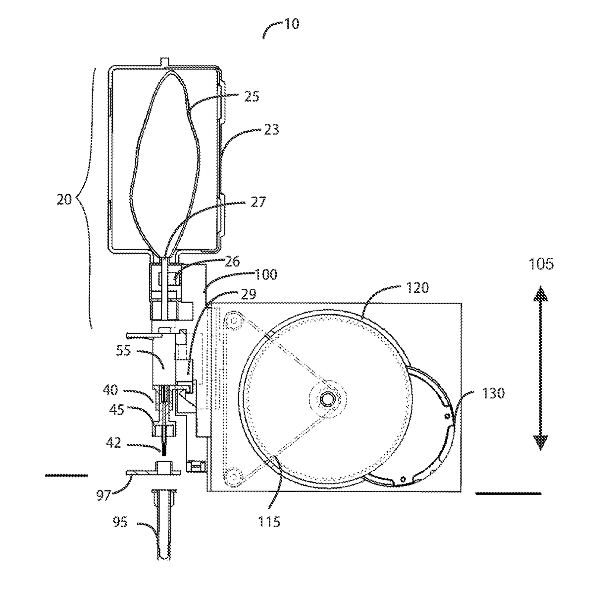
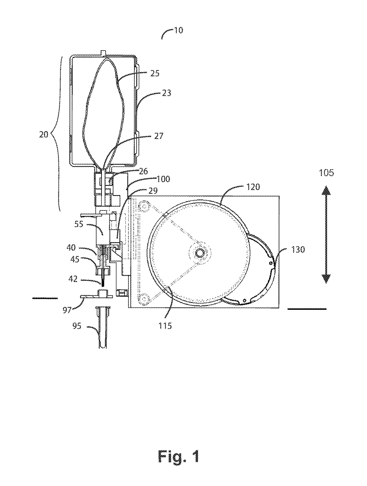
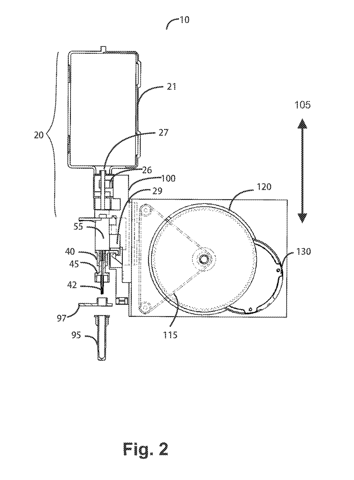
[0053]A disposable dispenser is disclosed which comprises a fluid reservoir, a pump chamber and at least one injection nozzle. The disposable dispenser may be part of a liquid handling device. The liquid handling device may be a diagnostic system or a part of a diagnostic system for analysing fluids for diagnostic purposes. The disposable dispenser unit may also be termed a disposable dispenser cartridge (DDC).

[0054]The terms fluid and liquid are used synonymously throughout the present application.

[0055]The fluid reservoir may be located above of, and is fluidly connected to, the pump chamber. The fluid reservoir may be located elsewhere than above, e.g. sideways, of the pump chamber. The pump chamber may be located above of, and is fluidly connected to, the injector nozzle. The pump chamber may be located elsewhere than above, e.g. sideways, of the injector nozzle. The fluid reservoir is fluidly connected to the pump chamber through a direct fluid connection, i.e. by fluidly conne...


PUM

PropertyMeasurementUnit
volumeaaaaaaaaaa
flexibleaaaaaaaaaa
dead volumeaaaaaaaaaa

Abstract

A disposable dispenser unit is disclosed. The disposable dispenser unit comprises a fluid reservoir, a tag for storing information, a dispenser head having a pump chamber and at least one injector nozzle, and a means disposed at the dispenser head for attachment thereof to a diagnostic system, wherein the pump chamber comprises a piston and the piston comprises a volume which can be filled with fluid.

Description

BACKGROUND OF THE INVENTION[0001]Field of the Invention[0002]The field of the invention relates to a dispensing device.[0003]Brief Description of the Related Art[0004]This disclosure teaches a liquid handling device, which is used, for example, in a diagnostic system for the dispensing of liquids into an analytical device. Known issues related to current liquid handling devices are a large dead volume of liquid within the liquid dispensing device which results in wasted fluid trapped in the dead volume. The fluid in the liquid dispensing device may also be instable due to the presence of ambient gasses that can lead to degradation of the liquid. There may also be an issue associated with confusion by the operator between the bottles and the tubing lines on prior art devices. There are also issues related to collection of debris on injector nozzles in the prior art devices, which can accumulate over time and lead to false results or result in malfunction.[0005]Current diagnostic syst...

Claims


Application Information

Patent Timeline
Patent Type & Authority Patents(United States)
IPC IPC(8): B65D83/38G01N35/10B01L3/02G01N35/00
CPCB65D83/38B01L3/0227G01N35/1002G01N35/1016B01L2200/143B01L2300/022B01L2400/0481G01N2035/00801G01N2035/1027
Inventor KUEHN, OLIVERTRUMP, MARTINBURKART, MICHAEL
Owner STRATEC BIOMEDICAL AG
Features
  • R&D
  • Intellectual Property
  • Life Sciences
  • Materials
  • Tech Scout
  • Unparalleled Data Quality
  • Higher Quality Content
  • 60% Fewer Hallucinations
Learn More