Supercharge Your Innovation With Domain-Expert AI Agents!

Chuck table and laser processing device

A chuck worktable and worktable technology, which is applied to auxiliary devices, laser welding equipment, metal processing equipment, etc., can solve the problems of high material cost, labor, cost, and burden of supporting parts.

Pending Publication Date: 2022-05-17
DISCO CORP
View PDF3 Cites 0 Cited by
  • Summary
  • Abstract
  • Description
  • Claims
  • Application Information

AI Technical Summary

Problems solved by technology

Therefore, it is necessary to prepare a somewhat thick member as a support member, and the burden of material costs for the support member is large.
In addition, if the support member is thick, the work and cost required for forming the concave portion or the fine hole on the support member will increase.
Therefore, if the replacement of the support member is performed frequently, the burden of the work of replenishing the support member for replacement increases.

Method used


Image

  • Chuck table and laser processing device
  • Chuck table and laser processing device
  • Chuck table and laser processing device

Examples


Embodiment Construction

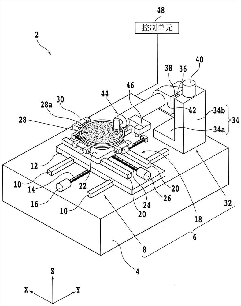
[0037] Hereinafter, an embodiment of one aspect of the present invention will be described with reference to the drawings. First, a configuration example of a machining device capable of mounting the chuck table of the present embodiment will be described. figure 1 It is a perspective view showing the laser processing device (first laser processing device) 2 . In addition, in figure 1 Here, the X-axis direction (machining feed direction, first horizontal direction) and the Y-axis direction (index feed direction, second horizontal direction) are directions perpendicular to each other. In addition, the Z-axis direction (vertical direction, vertical direction, and height direction) is a direction perpendicular to the X-axis direction and the Y-axis direction.

[0038] The laser processing device 2 has a base 4 that supports each component constituting the laser processing device 2 . The upper surface of the base 4 is formed along the horizontal direction (XY plane direction), ...


PUM

PropertyMeasurementUnit
thicknessaaaaaaaaaa

Abstract

The invention provides a chuck table and a laser processing apparatus, which can simply and inexpensively replace a holding surface for holding an object to be processed. The chuck table sucks and holds a workpiece, and is provided with: a base table having a suction path connected to a suction source; a support member which is attached to the base table and supports the workpiece; and a protective plate that is disposed so as to cover the upper surface of the support member and protects the support member, the protective plate having a plurality of through-holes that transmit the suction force from the suction source to the workpiece.

Description

technical field [0001] The present invention relates to a chuck table for attracting and holding a workpiece, and a laser processing device provided with the chuck table. Background technique [0002] In the manufacturing process of a device chip, a wafer is used in which devices are respectively formed in a plurality of regions divided by a plurality of dividing lines (lanes) arranged in a grid pattern. By dividing the wafer along planned dividing lines, a plurality of device chips each having a device can be obtained. Device chips are assembled in various electronic devices such as mobile phones and personal computers. [0003] A cutting device is used for dividing a wafer. The cutting device includes: a chuck table having a holding surface for holding a workpiece; and a cutting unit equipped with a ring-shaped cutting blade for cutting the workpiece. The wafer is held by the holding surface of the chuck table, and the cutting blade is rotated to cut into the wafer, the...

Claims


Application Information

Patent Timeline
Patent Type & Authority Applications(China)
IPC IPC(8): B23K26/70
CPCB23K26/702H01L21/6838H01L21/67092H01L21/67132B23K37/0408B23K37/0461B23K26/0853B23K26/364B23K26/10B23K2103/56B23K26/08
Inventor 增田幸容森数洋司
Owner DISCO CORP
Features
  • R&D
  • Intellectual Property
  • Life Sciences
  • Materials
  • Tech Scout
  • Unparalleled Data Quality
  • Higher Quality Content
  • 60% Fewer Hallucinations
Learn More