Bionics tooth planting body and implantation method thereof

一种种植体、仿生牙的技术,应用在人工牙系统领域,能够解决难以对抗扭力干扰、破坏有机骨结合、种植体松动种植等问题,达到提高种植成功率、扩大范围、提高的成功率的效果

Inactive Publication Date: 2008-08-27
赵大国
View PDF1 Cites 20 Cited by
  • Summary
  • Abstract
  • Description
  • Claims
  • Application Information

AI Technical Summary

Problems solved by technology

This patented technology is a typical cylindrical-conical rotary-in-place implant. Because it is a single cylinder or cone, it is impossible to form a mutual pulling effect between multiple roots of natural teeth to exert anti-rotation and anti-twist functions. Only relying on the limited initial stabilization of the implant surface thread, it is difficult to resist the various torsional interferences on the implant produced by the teeth on the implant base when chewing food
Therefore, at present, most of the implants still need to wait several months after being implanted in the human jawbone, and the teeth cannot be loaded immediately to perform the chewing function, otherwise the organic osseointegration of the contact interface between the implant and the jawbone will be destroyed, and eventually lead to implant loosening and implant failure

Method used


Image

  • Bionics tooth planting body and implantation method thereof
  • Bionics tooth planting body and implantation method thereof
  • Bionics tooth planting body and implantation method thereof

Examples


Embodiment 1

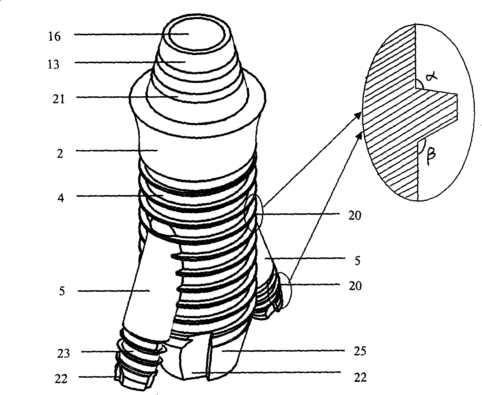
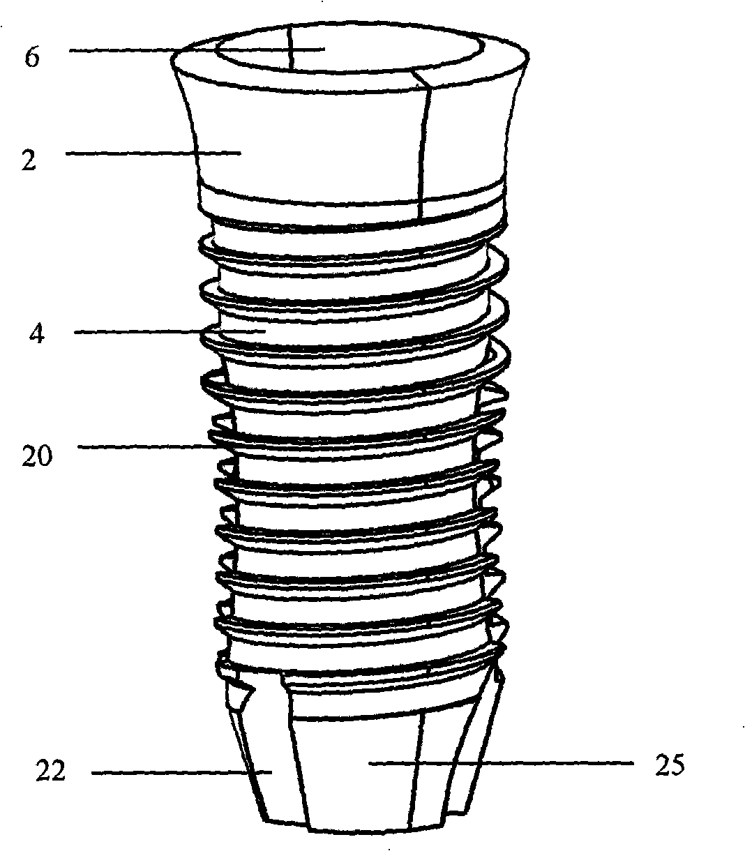
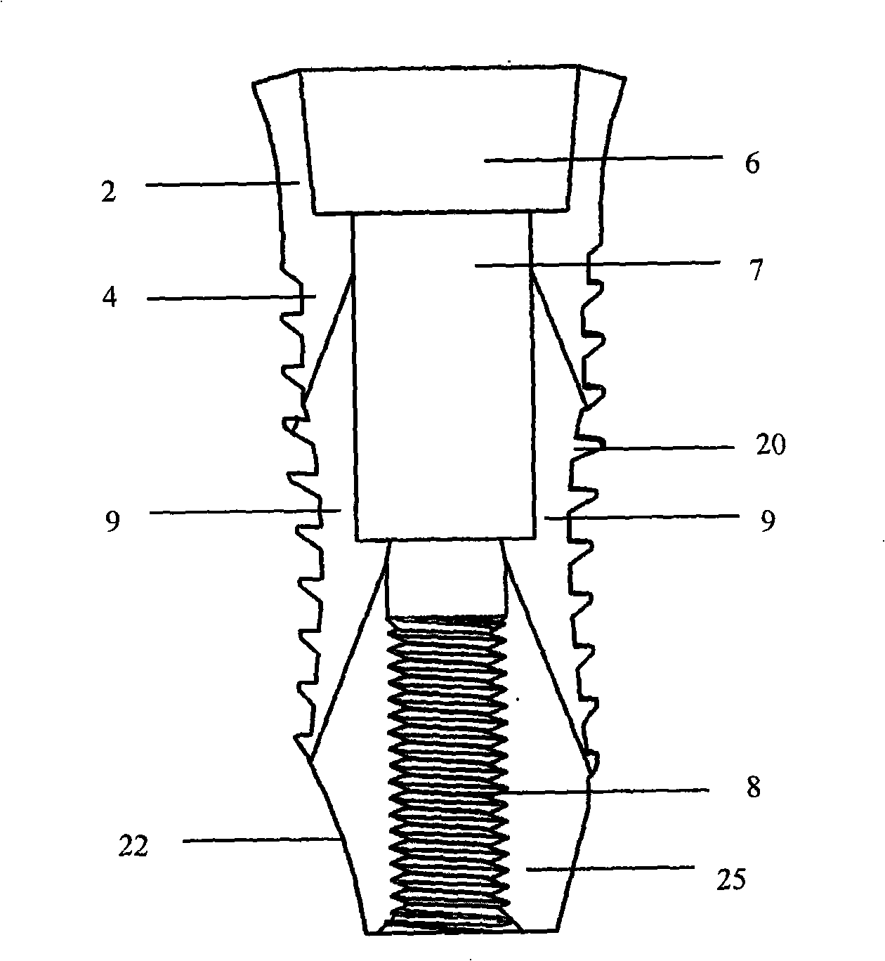
[0065] Such as figure 1 , figure 2 , image 3 , Figure 4 , Figure 5 , Figure 6 , Figure 7 , Figure 8 , Figure 9 , Figure 10 , Figure 11 , Figure 25 shown. The obtained female root 4 of the dental implant has a diameter of 4.8mm, and has threads 20 on its outer circumference. 102 degrees, the angle β between the lower surface of the tooth and the outer surface of the female root 4 is 123 degrees. The neck 2 is located above the female root 4 and is integrated with the female root 4; the neck 2 is in the shape of a truncated cone with a large top and a small bottom, that is, the diameter of the end close to the female root 4 is small, and the diameter of the end far away from the female root 4 is large ; The peripheral surface of neck 2 is smooth. The top of the neck 2 is provided with a tapered hole 6 inwardly, and the bottom of the tapered hole 6 is provided with an inner square hole 7 that gradually becomes thinner from the neck 2 to the female root 4, ...

Embodiment 2

[0069] Such as Figure 12 , Figure 13 , Figure 14 , Figure 15 , Figure 16 , Figure 17 , Figure 18shown. The obtained female root 4 of the dental implant has a diameter of 4.8mm, and has threads 20 on its outer circumference. 90 degrees, the angle β between the lower end surface of the corrugated tooth and the outer surface of the female root 4 is 123 degrees. The neck 2 is located above the female root 4 and is integrated with the female root 4; the neck 2 is in the shape of a truncated cone with a large top and a small bottom, that is, the diameter of the end close to the female root 4 is small, and the diameter of the end far away from the female root 4 is large ; The peripheral surface of neck 2 is smooth. The top of the neck 2 is provided with a taper hole 6 inwardly, and the bottom of the taper hole 6 is provided with an inner triangular hole 18 that gradually becomes thinner from the neck 2 to the female root 4, and the bottom of the inner triangular hole 1...

Embodiment 3

[0073] Such as Figure 19 shown. The same place as the first embodiment will not be repeated, the difference is that: the angle α between the upper end surface of the thread 20 on the outer circumference of the female root 4 and the outer surface of the female root 4 is 120 degrees. There is an oblique hole 9 on the side of the inner square hole 7, and the oblique hole 9 penetrates the outer periphery of the female root 4; The included angle α between the upper end surface of the threads 20 on the periphery of the lower end portion 23 of the sub-root and the outer surface of the sub-root 5 is 110 degrees. A dovetail slot 15 is provided on the side of the outer cube 14 , and the dovetail slot 15 is engaged with the dovetail tenon 11 . The angle between the mother root 4 and the child root 5 is 13 degrees.


PUM


Abstract

The invention discloses a bionic dental implant and an implanting method thereof. The bionic dental implant comprises a fixed root portion, a neck portion and an abutment portion. The fixed root portion consists of a primary root and at least one secondary root, and the diameter of secondary root is smaller than that of the primary root. The bionic dental implant further comprises oblique ports that are originated from the inside to the outside of the primary root and / or neck portion. The upper end of each secondary root is inserted in one of the oblique ports. Compared with the prior art, the bionic dental implant has excellent stability and anti-torsion ability in early stage after implantation, and has increased contact area with the jawbone. It has high success rates with respect to instant stress, long-term firmness, and effective masticatory function. The implanting method of the bionic dental implant is the same as the prior implanting method with operation via one implant port, so that the inventive implanting method retains simplicity and practicability of the prior operation of implanting the dental implant into jawbones, while obtaining obvious advantages of multi-root implantation.

Description

technical field [0001] The invention relates to an artificial tooth system, in particular to a bionic dental implant implanted into a jawbone as an artificial tooth root and an implantation method thereof. Background technique [0002] In terms of the convenience of clinical application and long-term stability, the most successful implant used by dentists at present is the cylindrical-conical rotary-in-place implant that resembles the shape of the natural tooth root. This kind of cylindrical or conical implant with axisymmetric shape generally has threads on its surface that can be rotated and located in the prepared jaw bone hole, so it can obtain a certain initial stability, and in addition to the implant surface Various means of increasing the biological contact area with the jawbone (such as surface roughening, titanium slurry spraying, etc.) have been implemented. At present, such implants have been commonly used around the world. [0003] The notification number is CN...

Claims


Application Information

Patent Timeline
Patent Type & Authority Applications(China)
IPC IPC(8): A61C8/00
CPCA61C8/001A61C8/0018A61C8/0043A61C8/005A61C8/0054A61C8/0066A61C8/0068A61C8/0069
Inventor 赵大国
Owner 赵大国
Why Eureka
Try Eureka