Air-lift type circular current reactor

A loop reactor and airlift technology, applied in chemical methods, chemical instruments and methods, and chemical/physical processes for reacting liquids and gaseous media, can solve the problem of reducing the gas-liquid contact area and increasing the volume of the reactor , Reactor utilization efficiency decline and other issues, to achieve the effect of improving efficiency and strengthening gas-liquid mass transfer

Inactive Publication Date: 2008-08-27
SINOPEC YANGZI PETROCHEM
View PDF1 Cites 28 Cited by
  • Summary
  • Abstract
  • Description
  • Claims
  • Application Information

AI Technical Summary

Problems solved by technology

When the height-to-diameter ratio continues to increase, the gas holdup in the middle and lower part of the annulus between the reactor tower and the draft tube is very small due to the high reactor, so the gas-liquid contact area decreases and the utilization efficiency of

Method used


Image

  • Air-lift type circular current reactor
  • Air-lift type circular current reactor
  • Air-lift type circular current reactor

Examples


Embodiment 1

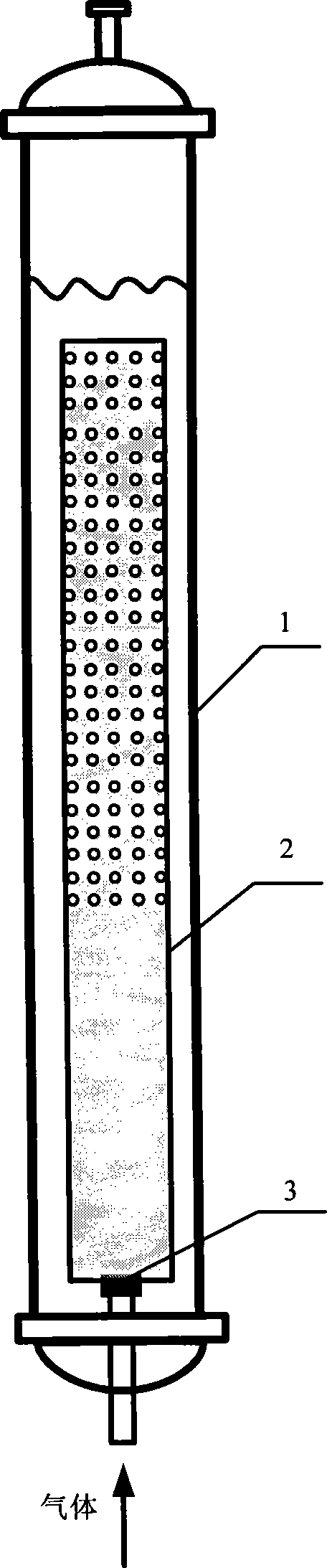
[0034] Example 1 This example is about the hydrodynamic conditions in a 180L loop reactor. The height of the reactor tower is 3000mm, and the inner diameter is 270mm. The height of the guide tube is 2200mm, the inner diameter is 210mm, and the distance from the lower edge of the guide tube to the bottom of the reactor is 100mm. The opening section of the diversion cylinder is cylindrical, with a height of 1300mm, and 1120 circular holes with a diameter of 5mm are evenly opened, and the total area of ​​the holes is 61% of the cross-sectional area of ​​the diversion cylinder. After the reactor is filled with water containing 0.5% ethanol, the overall gas holdup of the reactor under different superficial gas velocities (compared with the reactor with the same structure but without openings in the draft tube) is shown in Table 1. The distribution of the rate along the axial direction (at the gas velocity u G =1.44cm·s -1 ) is shown in Figure 6 (compared with a reactor with the ...

Embodiment 2

[0037] Example 2 This example is the effect of the opening area on the hydrodynamic conditions in the reactor in a 180L loop reactor. The structural parameters and experimental system of the reactor are the same as in Example 1. The ratio of the total opening area to the cross-sectional area of ​​the guide cylinder (S p / S t ) is 61%, 32%, 16% (uniform distribution), superficial gas velocity u G =1.44cm·s -1 , the overall gas holdup of the reactor is shown in Table 2, and the distribution of the annulus gas holdup along the axial direction is shown in Table 2. Figure 7 , see S p / S t <0.3, the distribution effect of gas holdup becomes significantly worse.

[0038] The overall gas holdup of the reactor when the opening area is different in table 2

[0039] S p / S t / %

Embodiment 3

[0040] Example 3 This example is about the effect of the height of the opening section on the hydrodynamic conditions in the reactor in a 180L loop reactor. Other structural parameters and experimental system of the reactor are the same as in Example 1, and the superficial gas velocity u G=1.44cm·s -1 , the height of the opening section H p When they are 800mm, 1300mm, and 1600mm respectively, the corresponding ratio to the total height of the guide tube (H p / H t ) are 0.36, 0.59, 0.73, the overall gas holdup of the reactor is shown in Table 3, and the distribution of the annulus gas holdup along the axial direction is shown in Table 3. Figure 8 , see H p / H t Not bigger is better, in this embodiment when H p =1600mm, at the bottom of the hole section, not only does no gas flow out of the guide tube, but the gas in the annulus descends to the bottom of the hole section, and then flows into the guide tube from the hole, resulting in the gas contained in the bottom of th...


PUM

PropertyMeasurementUnit
The inside diameter ofaaaaaaaaaa

Abstract

A loop reactor with a porous guide flow cylinder is applied in gas-liquid two-phase reaction or gas-liquid-solid three-phase reaction and belongs to chemical reaction engineering field. The guide flow cylinder is characterized in including an upper sealing section and a lower hole opened section. Distribution holes are opened on the hole opened section at a certain ratio, and both gas and liquid can flow out of the holes. After gas enters the guide flow cylinder through a gas distributor, gas and liquid flow out of the gas distribution holes of the hole opened section and the top of the guide flow cylinder and downwards into the guide flow cylinder from the bottom of the guide flow cylinder to form a circulation flow. Gas flowing out of the hole opened section is carried by fluid and descends to the reactor bottom. Even when the height/diameter ratio of the reactor is larger, the reactor bottom can have a high gas content. Therefore, the multi-hole guide flow cylinder breaks through a limit of a conventional circulation flow reactor on height/diameter ratio, and satisfies requirement of height/diameter ratio of a circulation flow reactor in industrial application.

Description

technical field [0001] The invention relates to a reactor used for two-phase reaction of gas and liquid or three-phase reaction of gas, liquid and solid, which belongs to the field of chemical reaction engineering, specifically, it is an air-lift loop reactor with a porous guide tube structure. Background technique [0002] The air-lift loop reactor developed based on the bubble reactor is to add an internal member guide tube in the bubble reactor to make the fluid circulate around the guide tube in the reactor, so as to realize the gas, liquid The three phases of solid and solid are evenly mixed, and a high interphase mass transfer coefficient can be obtained. It is widely used in many gas, liquid and solid three-phase reactions and gas and liquid absorption reactions such as biological fermentation process and sewage treatment process. [0003] In general, the height-to-diameter ratio of the airlift loop reactor is small, about 6-8. When the height-to-diameter ratio conti...

Claims


Application Information

Patent Timeline
IPC IPC(8): B01J8/02B01J10/00
Inventor 姚小利丁富新汪洋蒋国强李晓强刘建新王保正周启惠
Owner SINOPEC YANGZI PETROCHEM
Why Eureka
Try Eureka