Lubricating and cooling system for vibrating roller

A vibratory roller, lubricating and cooling technology, applied in the direction of engine lubrication, engine components, lubricating parts, etc., can solve the problems of increased loss, large heat generation, bearing bearing damage, etc., to reduce heat and energy loss, and reduce deformation degree, the effect of simple structure

Inactive Publication Date: 2008-08-27
屠卫东
View PDF0 Cites 14 Cited by
  • Summary
  • Abstract
  • Description
  • Claims
  • Application Information

AI Technical Summary

Problems solved by technology

The vibration mechanism of existing road rollers usually adopts splash type or wall flow type lubrication methods. These lubrication methods have defects such as insufficient lubrication, large energy

Method used


Image

  • Lubricating and cooling system for vibrating roller
  • Lubricating and cooling system for vibrating roller
  • Lubricating and cooling system for vibrating roller

Examples


Embodiment Construction

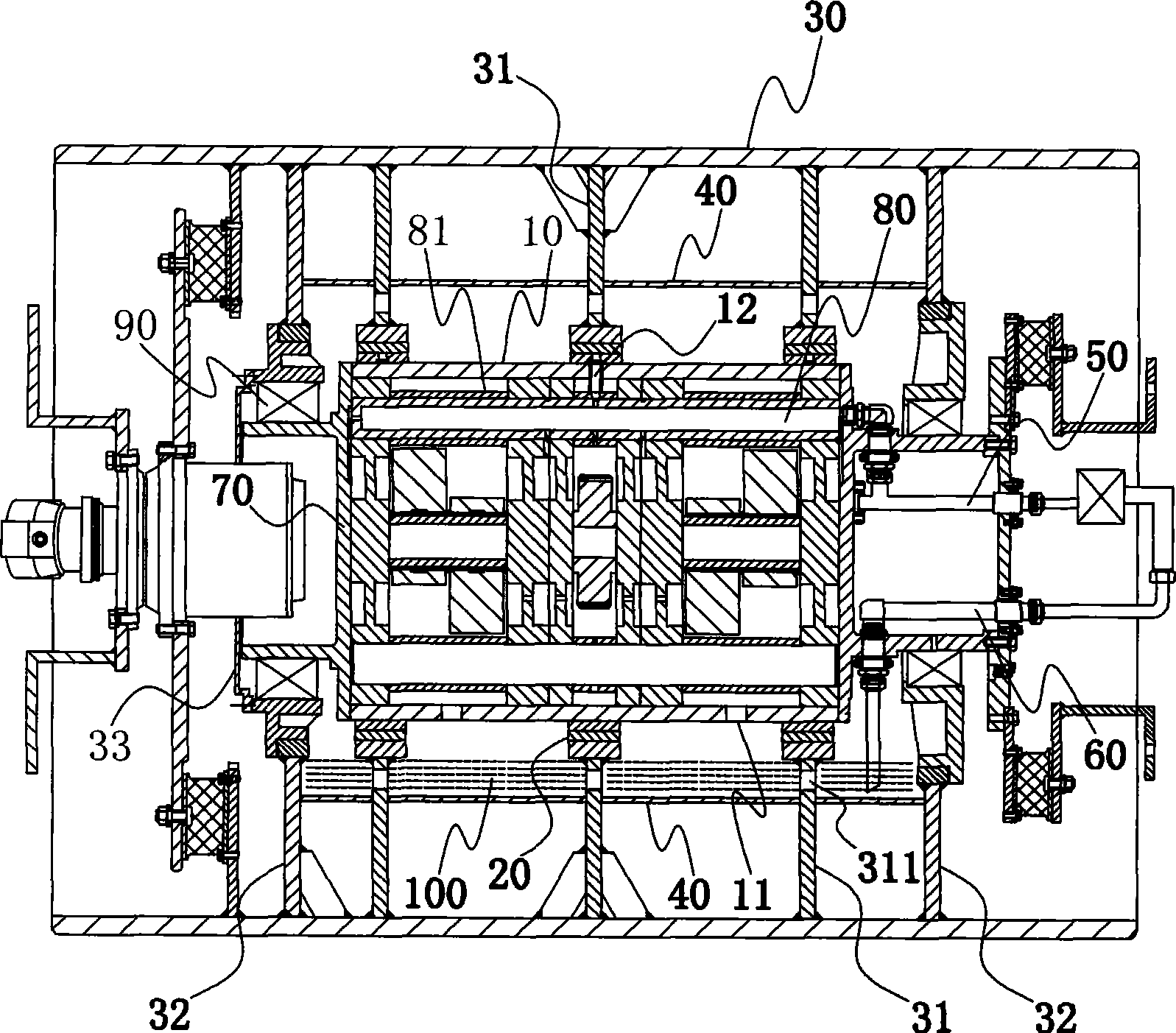
[0009] Such as figure 1 As shown, a lubricating and cooling system for a vibratory roller includes an oil pump assembly fixed on the body of the roller. The vibration exciter shell 10 and the roller body 30 are formed by bearings for rolling fit. The inside of the exciter is fixed with a vibration The fixed shaft 80 positioned by each bearing seat of the wheel assembly, the pressure lubricating oil is transported to the oil chamber inside the fixed shaft 80 through the oil supply pipe 50 of the oil pump assembly, and enters the lubricating oil of each bearing through the opening on the wall of the fixed shaft 80 Road, and then flow through each lubricating oil channel to the opening 11 on the bottom of the exciter housing 10, and converge to the bottom end surface of the roller body 30 to form an oil pool 100, the lubricating oil in the oil pool 100 passes through the oil suction pipe 60 is drawn back to the oil pump to form a complete circulating lubrication path.

[0010] D...


PUM


Abstract

The invention belongs to the mechanical field of road rollers, in particular to a lubricating cooling system of a vibratory roller. The invention comprises an oil pump assembly which is fixed on the body of the road roller, a vibration exciter shell and a wheel body of the road roller are formed into a rolling matching by a bearing, and a fixed shaft which is used to locate each bearing seat of a vibrating wheel assembly is fixed in the inner side of the vibration exciter. Pressure lubricating oil is transported into an oil cavity which is arranged in the inner portion of the fixed shaft through an oil supply pipe of the oil pump assembly, enters into an oil passage of each bearing through an opening which is arranged on the wall surface of the fixed shaft, and then flows into the opening which is arranged on the bottom portion of the vibration exciter shell through each oil passage and is converged on the bottom end surface in the wheel body of the road roller to form an oil basin, and the lubricating oil in the oil basin is pumped to the oil pump by an oil suction pipe to form a whole cycle lubrication path. The lubricating cooling system of the vibratory roller has simple structure and full lubrication.

Description

technical field [0001] The invention belongs to the mechanical field of road rollers, and in particular relates to a lubricating and cooling system of a vibratory road roller. Background technique [0002] Vibratory rollers are the key equipment for high-grade road construction at present. The bearings of the vibrating mechanism bear huge pulse loads. Therefore, the supporting bearings of the vibrating mechanism must be fully lubricated to make the vibratory roller operate normally. The vibration mechanism of existing road rollers usually adopts splash type or wall flow type lubrication methods. These lubrication methods have defects such as insufficient lubrication, large energy loss, and large heat generation, which will cause premature damage to the bearing bearing, thus affecting the road roller. The normal work reduces the production efficiency and increases the loss. Contents of the invention [0003] The purpose of the present invention is to provide a lubricating ...

Claims


Application Information

Patent Timeline
IPC IPC(8): E01C19/28F16N39/02
Inventor 屠卫东
Owner 屠卫东
Why Eureka
Try Eureka