Drill site tubular pile automatic discharging device

An automatic discharge and string technology, applied in the direction of drill pipe, casing, drilling equipment, etc., can solve the problems of potential safety hazards, low operating efficiency, heavy workload of operators, etc., to achieve strong applicability, convenient horizontal transportation, The effect of easy removal

Active Publication Date: 2008-08-27
CHINA NAT OFFSHORE OIL CORP +1
View PDF8 Cites 20 Cited by
  • Summary
  • Abstract
  • Description
  • Claims
  • Application Information

AI Technical Summary

Problems solved by technology

It can be seen from the above process that the catwalk 53 is fixed, and the pipe string 4 is pushed onto the slideway 52, then pulled onto the catwalk, and finally pushed onto the pipe frame 54. This series of processes all require manual adjustment of the pipe string. 4 to operate, a

Method used


Image

  • Drill site tubular pile automatic discharging device
  • Drill site tubular pile automatic discharging device
  • Drill site tubular pile automatic discharging device

Examples


Embodiment Construction

[0023] The present invention will be described in detail below in conjunction with the accompanying drawings and embodiments.

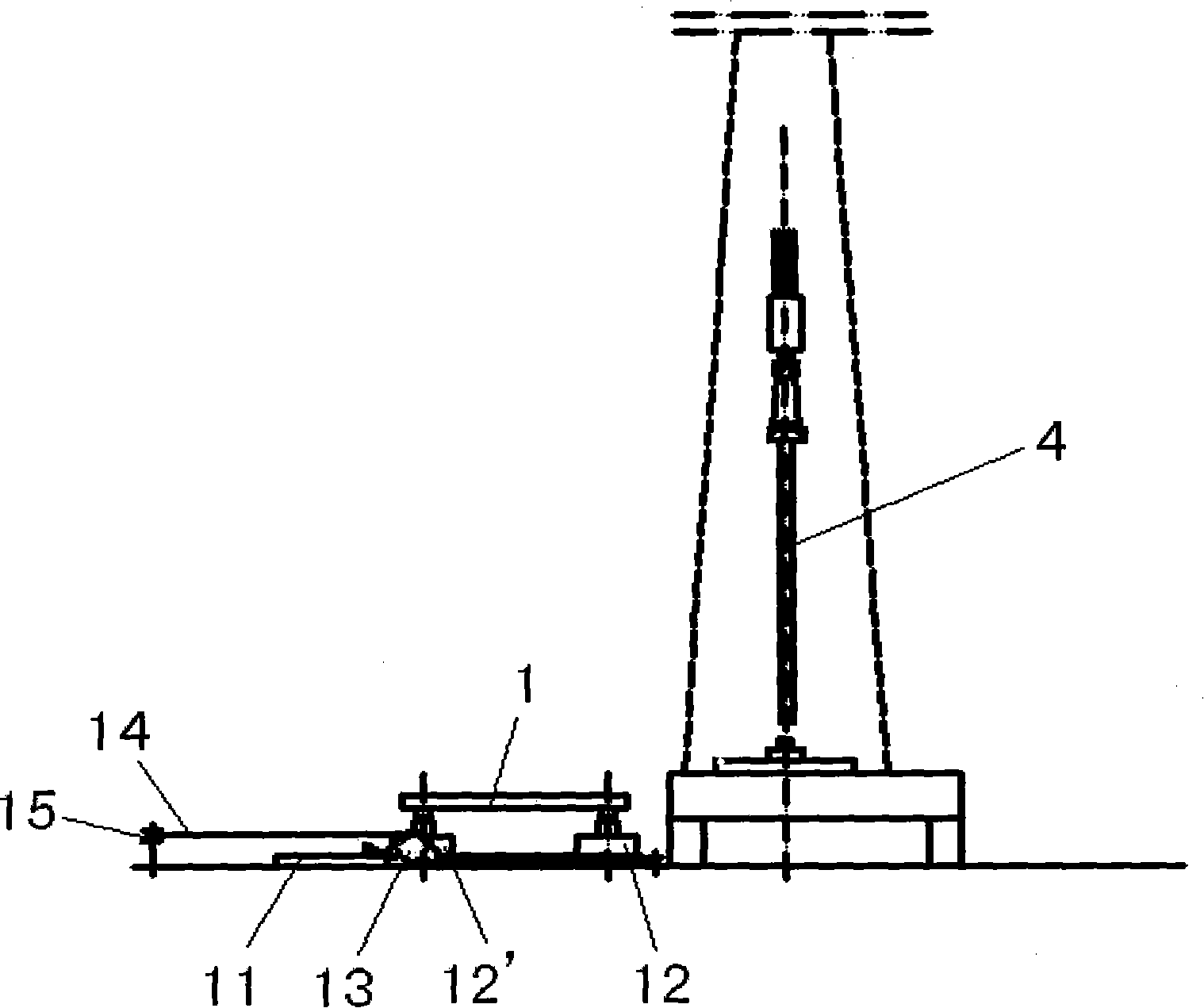
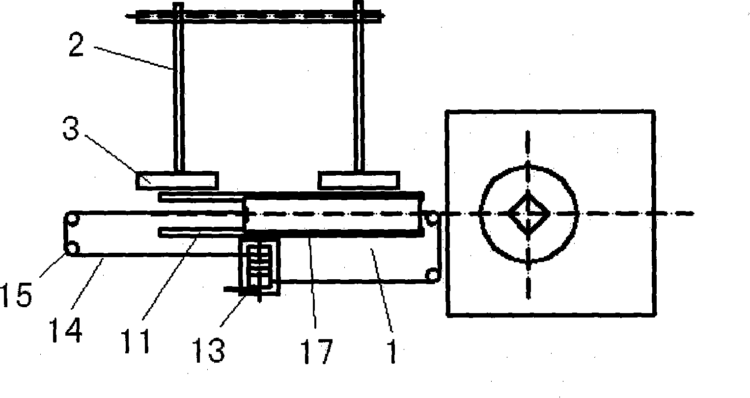
[0024] like figure 2 , image 3 As shown, the present invention includes a mobile lifting device 1 and a multi-layer pipe rack 2, and may also include a lifting pipe bridge 3. The mobile lifting device 1 includes a track 11, on which two lifting cylinders 12, 12' are slidably arranged, and a pneumatic winch 13 is set on one side of the track 11, and the pneumatic winch 13 passes a wire rope 14 and a plurality of pulleys 15 A dragging device for controlling the movement of the two lift cylinders 12, 12' is formed.

[0025] like Figure 4 , Figure 5 , Image 6 As shown, the tops of the plungers of the two lifting cylinders 12, 12' are connected to a pair of baffle plates forming the slideway 17 through a pivot 16, and a spring return cylinder 18 is respectively installed between the two baffle plates of the slideway 17 and the plungers. , the dri...


PUM


Abstract

The invention relates to an automatic string handling device in well fields, being characterized in comprising a movable lifting device and a multi-layer pipe rack, the movable lifting device comprises a rail on which two lifting cylinders are arranged in a sliding way and one side of which a dragging device used to drag two lifting cylinders is arranged, the tops of plunger pistons of the two lifting cylinders are respectively connected with a set of runners rotationally through a driving device; one side of the movable lifting device is provided with the multi-layer pipe rack. The automatic string handling device in well fields can also be provided with a lifting pipe bridge between the movable lifting device and the multi-layer pipe rack; realizes the automation of the link of handling strings, is strongly applicable and can be used in similar automatic handling operation.

Description

technical field [0001] The invention relates to a pipe string discharge device, in particular to an automatic well site pipe string discharge device used in drilling and workover operations. Background technique [0002] At present, in our country, when drilling and workover operations on oil well sites, the discharge of pipe strings needs to be done manually by workers. During the operation (as shown in Figures 1a to 1d), one end of the pipe string 4 is first clamped with a spreader and lowered to the drill floor surface 51. When the bottom end of the pipe string 4 is close to the drill floor surface 51, the pipe string 4 is manually pushed to the On the slideway 52, when the top of the pipe string 4 is lowered close to the drill floor, the spreader is removed, and then the pipe string 4 is manually pulled onto the catwalk 53 (as shown in Figure 1c), and then the pipe string is pulled from the catwalk 53 4Push onto the tube holder 54. It can be seen from the above process...

Claims


Application Information

Patent Timeline
IPC IPC(8): E21B19/14
Inventor 姜伟刘健付英军
Owner CHINA NAT OFFSHORE OIL CORP
Why Eureka
Try Eureka