Oil pump pressure control device

A pressure control and oil pump technology, applied in pump control, pumps, rotary piston pumps, etc., can solve the problems of no reduction, noise, and vibration overlap, and achieve the goal of reducing sliding area, reducing useless work, and improving pump efficiency Effect

Inactive Publication Date: 2008-08-27
YAMADA SEISAKUSHO KK
View PDF3 Cites 15 Cited by
  • Summary
  • Abstract
  • Description
  • Claims
  • Application Information

AI Technical Summary

Problems solved by technology

In addition, since two discharge sources are discharged from the same rotor, the timing of the discharge pulsation overlaps, and there is also a disadvantage that noise and vibration overlap and become larger.
In addition, since there is one set of rotors, there is a disadvantage that even if waste work is generated, there is no mechanism for reducing waste work in the rotor.

Method used


Image

  • Oil pump pressure control device
  • Oil pump pressure control device
  • Oil pump pressure control device

Examples


Embodiment Construction

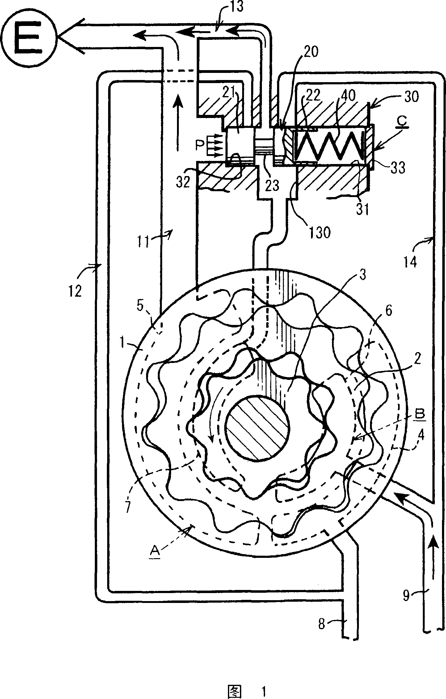
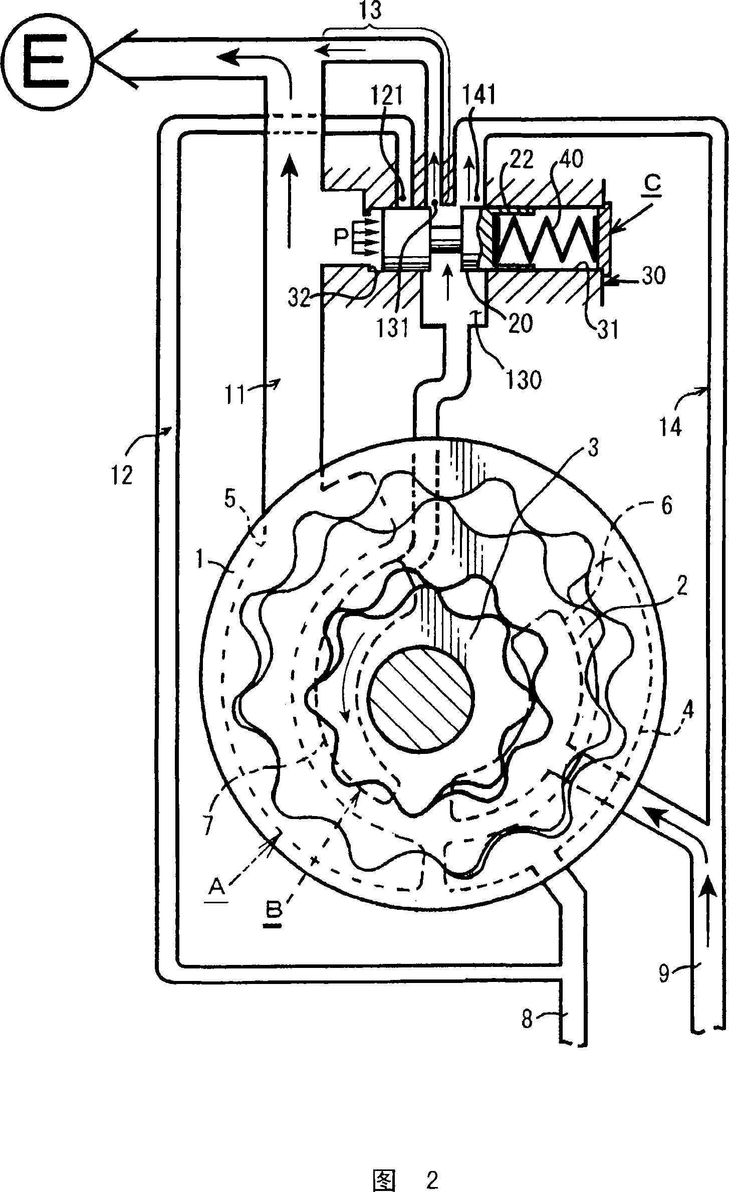
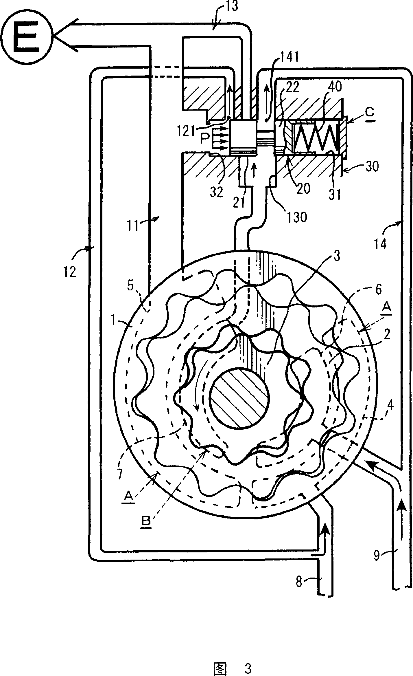
[0038] Hereinafter, embodiments of the present invention will be described with reference to the drawings. Each figure shows a three-rotor type oil pump mainly including an outer rotor 1 , an intermediate rotor 2 and an inner rotor 3 . The outer rotor 1 and the intermediate rotor 2 are provided with an outer suction port 4 and an outer discharge port 5 , and the intermediate rotor 2 and the inner rotor 3 are provided with an inner suction port 6 and an inner discharge port 7 . The outer rotor 1, the intermediate rotor 2, the outer suction port 4, and the inner suction port 5 are collectively referred to as the outer rotor, and the intermediate rotor 2, the inner rotor 3, the inner suction port 6, and the inner discharge port. 7 are collectively referred to as inner peripheral rotors.

[0039] In the oil pump of the three-rotor type, the first discharge passage 11 for supplying oil to the engine E from the outer peripheral side discharge port 5, the first return passage 12 for ...


PUM


Abstract

The invention provides a flow quantity variable oil pump having two discharge ports and using three rotors. The inventive oil pump maintains pressure property same with that of normal oil pumps and reduces friction at the same time. The inventive oil pump comprises a first discharge passage (11) for supply oil to the engine; a return passage (E) that returns to an intake side of an outer circumferential side rotor (A); a second discharge passage (13) for supplying oil to the engine; a return passage (E) that returns to an intake side of an inner circumferential side rotor (B); and a pressure control valve whose valve main body is provided between a discharge port from the inner circumferential side rotor and the first discharge passage. The first and second discharge passage are coupled, and a flow passage control is executed in each of: a low revolution range in a state in which only the first and the second discharge passage are open; an intermediate revolution range in a state in which the first and second discharge passage are open and a first intake side of the return passage is closed while a second intake side of the return passage is open; and a high revolution range in a state in which the second discharge passage is closed while the first discharge passage and the return passage are open.

Description

technical field [0001] The present invention relates to a pressure control device of an oil pump. In a variable flow rate type oil pump having two discharge ports and using three rotors as a mechanism for providing the two discharge sources, the method is improved by improving the oil passage switching method. The pressure (oil pressure) characteristic is not a multi-stage characteristic but can reduce friction while maintaining the same characteristic as the pressure characteristic of a general oil pump. Background technique [0002] Conventionally, according to Patent Document 1, three rotors themselves are known as a mechanism for sending oil to two places. In Patent Document 1, only a mechanism for sending oil to two places is shown, and other effects are not shown. [0003] (Patent Document 1) Japanese Patent Laid-Open No. 11-280666 [0004] (Patent Document 2) Japanese Patent Laid-Open No. 2005-140022 [0005] (Patent Document 3) Japanese Patent Laid-Open No. 2002-7...

Claims


Application Information

Patent Timeline
Patent Type & Authority Applications(China)
IPC IPC(8): F04C14/24F04C14/00F04C2/10F04C11/00
CPCF04C2/10F04C14/065F04C14/26
Inventor 甲斐圭一藤木谦一小野靖典
Owner YAMADA SEISAKUSHO KK
Why Eureka
Try Eureka