Novel hydraulic motor transmission control valve group

A technology of hydraulic motor and transmission control, applied in servo motor components, fluid pressure actuating devices, mechanical equipment, etc., can solve problems such as complex structure, and achieve the effect of reducing pipelines, shortening pipelines, and reducing energy consumption

Inactive Publication Date: 2008-08-27
康凤明
View PDF0 Cites 3 Cited by
  • Summary
  • Abstract
  • Description
  • Claims
  • Application Information

AI Technical Summary

Problems solved by technology

At present, the hydraulic brake (or clutch) control valve of the hydraulic motor transmission is often set independently and connected by pipes, and the structure is relatively complicated.

Method used


Image

  • Novel hydraulic motor transmission control valve group
  • Novel hydraulic motor transmission control valve group
  • Novel hydraulic motor transmission control valve group

Examples


Embodiment Construction

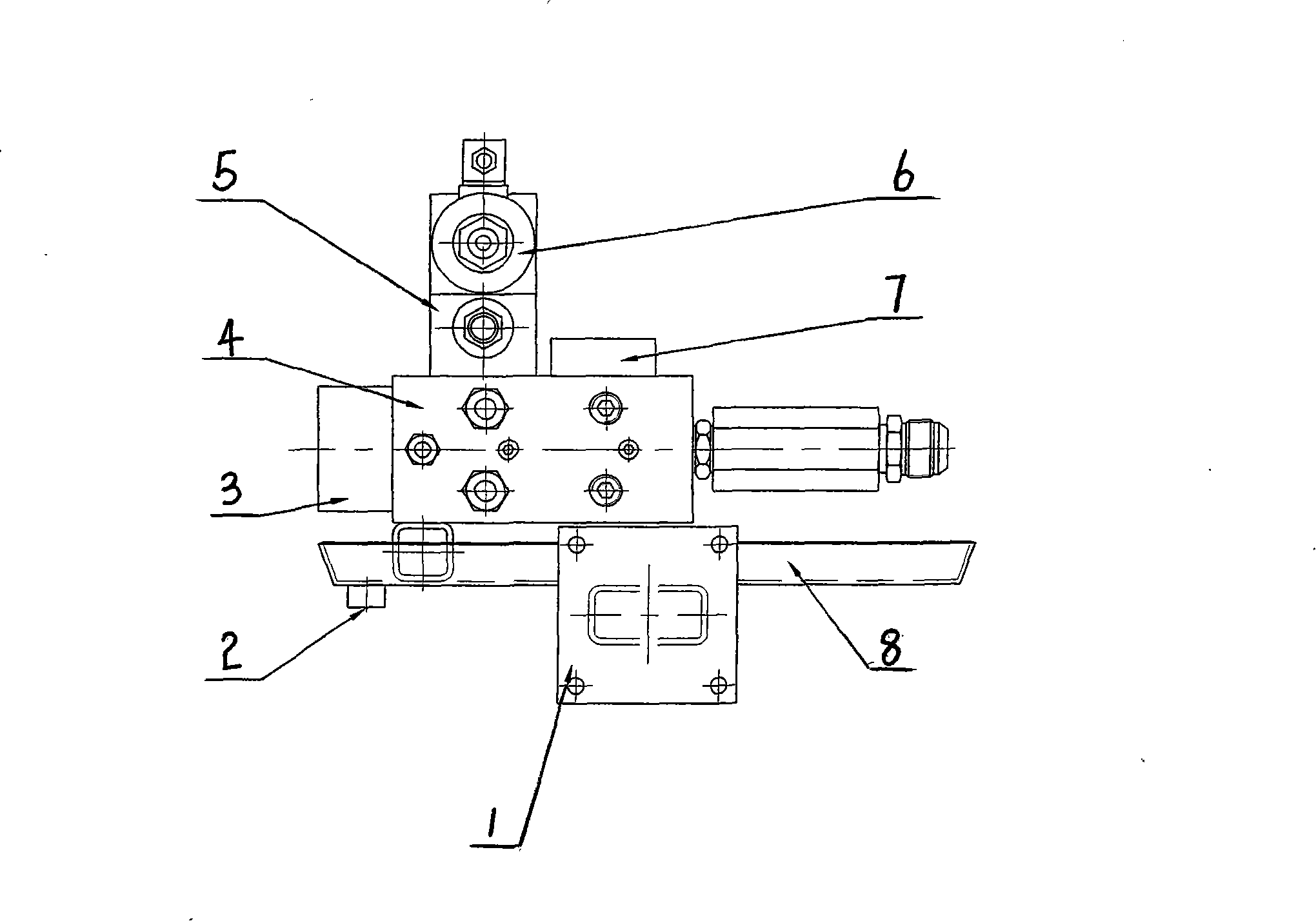
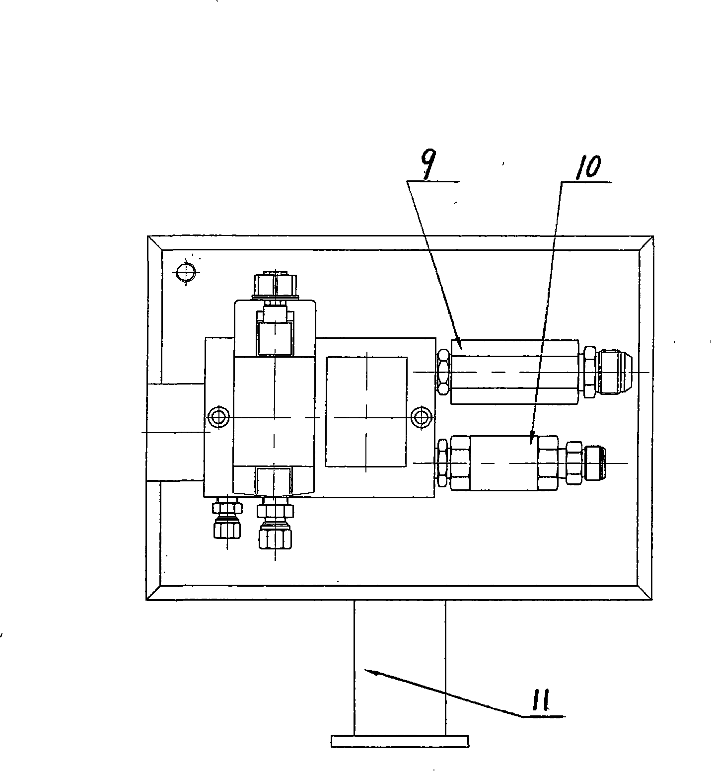
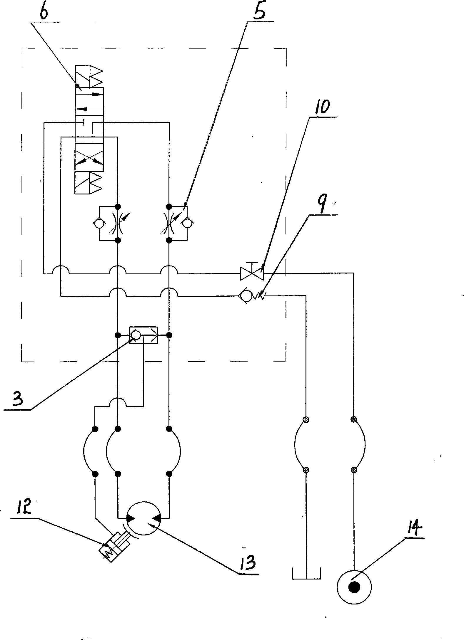
[0009] from figure 1 The structure schematic diagram and figure 2 It can be seen from the top view that the present invention mainly includes electromagnetic reversing valve 6, one-way throttle valve 5, shuttle valve 3, stack valve 7, one-way valve 9, ball valve 10, connecting valve block 4, oil receiving plate 8 and pipe Connectors etc. Brake (clutch) cylinder control valve adopts shuttle valve built-in two-way cartridge valve cover plate, electromagnetic reversing valve 6, one-way throttle valve 5, shuttle valve 3, stacking valve 7, one-way valve 9, ball valve 10 Installed on the connecting valve block 4, each control valve is connected with the connecting valve block 4 by pipe joints. The connecting valve block 4 is a metal cuboid, on which corresponding oil holes and threaded holes for installation and fastening are processed according to the specifications of various hydraulic valves and pipe joints installed, and several connecting channels are processed inside, so th...


PUM


Abstract

The invention discloses a novel hydraulic motor transmission control valve bank which comprises an electromagnetic directional valve, a one-way throttle valve, a shuttle valve, an overlapped valve, a one-way valve and a ball valve, wherein each control valve is arranged on a junction valve block; a braking oil cylinder control valve adopts a shuttle valve built-in type two-way cartridge valve cover board; the junction valve block is arranged on the upper part of a drip pan; the inside of the junction valve block has a plurality of channels and oil holes; moreover, one side of the drip pan is provided with a fixing device. The novel hydraulic motor transmission control valve bank which has a simple structure can be arranged near the transmission device of a hydraulic motor, thereby reducing pipes and energy consumption.

Description

Technical field: [0001] The invention belongs to the technical field of hydraulic transmission, and in particular relates to a control valve group of a novel hydraulic motor transmission device. Background technique: [0002] The hydraulic motor transmission device is a widely used basic part of hydraulic transmission. It is generally composed of a hydraulic motor, a hydraulic brake (or clutch), a gear reducer, etc. The hydraulic system needs to control the start and stop of the motor, forward and reverse and The rotation speed controls the brake (or clutch) of the hydraulic brake (or clutch). At present, the hydraulic brake (or clutch) control valve of the hydraulic motor transmission device is often set independently and connected by pipes, and the structure is relatively complicated. Invention content: [0003] The object of the present invention is to provide a novel hydraulic motor transmission control valve group which can be arranged near the hydraulic motor transm...

Claims


Application Information

Patent Timeline
Patent Type & Authority Applications(China)
IPC IPC(8): F15B13/02
Inventor 郑轶明朱洪臣
Owner 康凤明
Why Eureka
Try Eureka