Eureka AIR delivers breakthrough ideas for toughest innovation challenges, trusted by R&D personnel around the world.

System and method for controlling emergency draft of air conditioner

A ventilation control system and control method technology, which is applied in heating and ventilation control systems, heating and ventilation safety systems, space heating and ventilation, etc., and can solve problems such as complex circuit structure, low fan speed, and guaranteed compartment ventilation , to achieve the effect of simplifying the system circuit and improving the level of integration

Inactive Publication Date: 2008-08-27
SHANDONG LONGERTEK TECH CO LTD
View PDF0 Cites 8 Cited by
  • Summary
  • Abstract
  • Description
  • Claims
  • Application Information

AI Technical Summary

Problems solved by technology

[0005] The existing air conditioner emergency ventilation control method is only the switching of the DC and AC circuits. Both the DC and AC circuits are equipped with their own filter circuits and inverters. The overall circuit structure is complex, which is not conducive to the integration and miniaturization of the control circuit.
[0006] Moreover, the emergency ventilator is driven by a low-frequency, low-voltage three-phase AC power supply through DC110V DC inverter, so the speed of the ventilator is low, which is not conducive to ensuring the ventilation in the compartment in an emergency

Method used


Image

  • System and method for controlling emergency draft of air conditioner
  • System and method for controlling emergency draft of air conditioner
  • System and method for controlling emergency draft of air conditioner

Examples


Embodiment 1

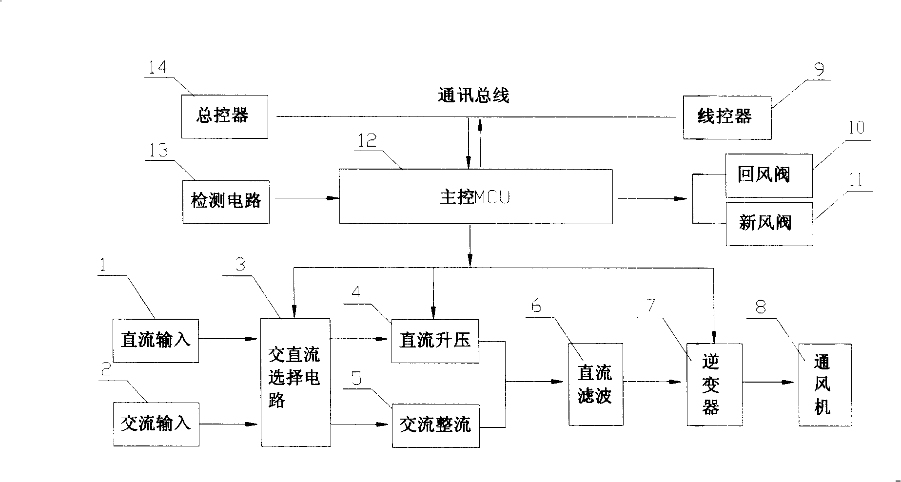
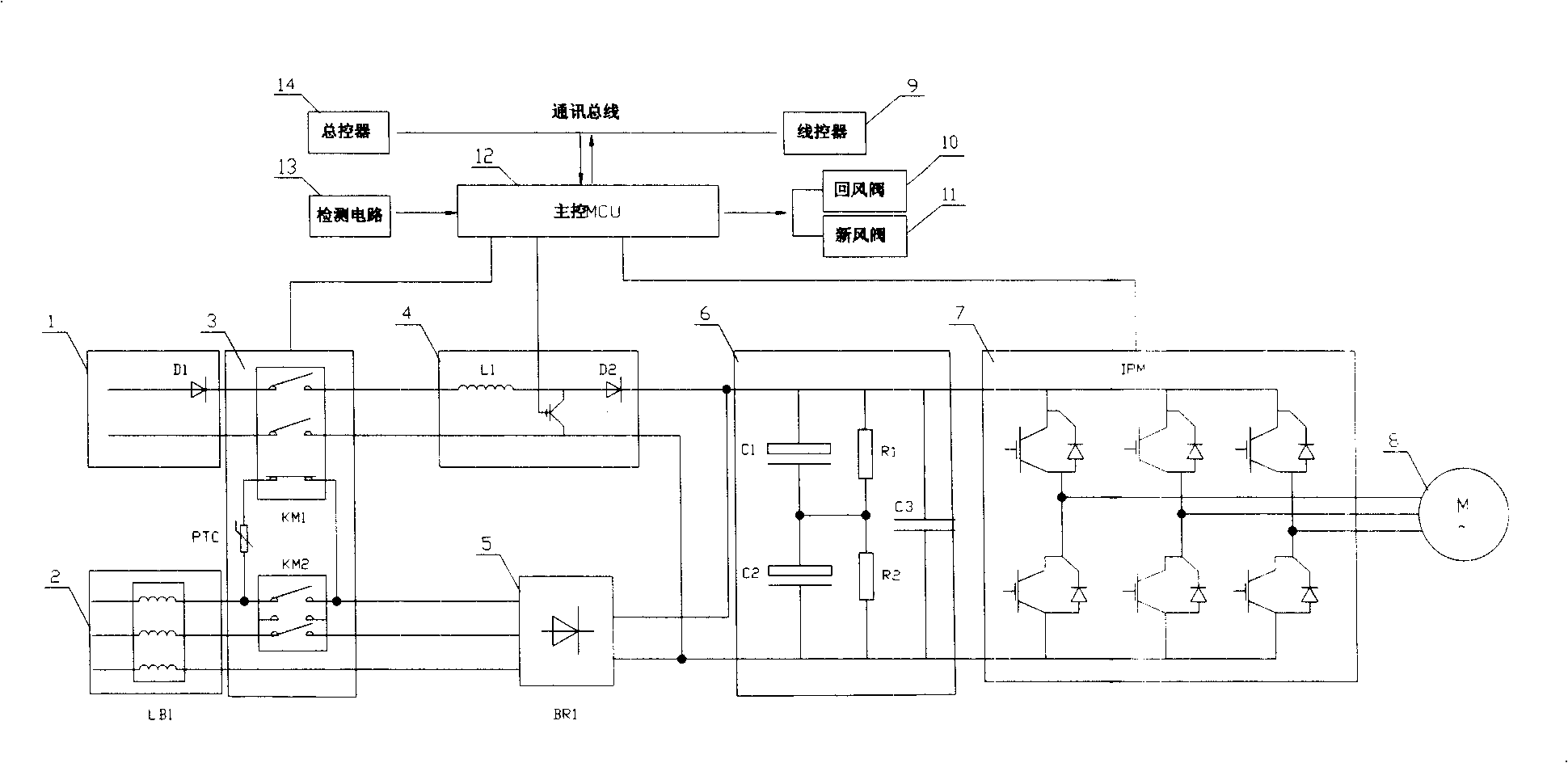
[0037] Example 1, such as Figure 2 to Figure 4 As shown, the air conditioner emergency ventilation control system mainly includes a DC input circuit 1, an AC input circuit 2, an AC / DC selection circuit 3, a DC boost circuit 4, an AC rectifier circuit 5, a DC filter 6, and an inverter 7 , Ventilator 8, wire controller 9, return air valve 10, fresh air valve 11, main control MCU 12, detection circuit 13 and master controller 14.

[0038] Wherein, the AC input circuit 2 is connected to the AC rectification circuit 5 through the AC and DC selection circuit 3 .

[0039] The DC input circuit 1 is connected to the DC boost circuit 4 through the AC and DC selection circuit 3 , the output of the DC boost circuit 4 is connected in parallel with the output of the AC rectifier circuit 5 , and then connected to the DC filter circuit 6 .

[0040] The DC filter circuit 6 is connected to the ventilator 8 through the inverter 7, and the main control MCU circuit 12 is respectively connected t...


PUM


Abstract

The invention provides a control system for emergency ventilation for an air conditioning and a method thereof, adopting a circuit design of a filter circuit and an inverter structure which are used by a direct current loop and an alternating current loop in common, and driving the emergency ventilator to operate by a three-phase alternating-current supply with a higher frequency and a higher voltage value performing an inversion after the direct current is boosted. Integrated detecting and switching loops of alternating current and direct current are adopted, and the alternating current and the direct current use the same group of the filter circuit and the inverter in common to achieve the simplification of a circuit structure and improve the integration capability of the control system. Alternating current and direct current option circuits of the control system comprises contacts (KM1), (KM2) and a thermistance, wherein a main contact of the contactor (KM1) is connected in a loop of a direct current input circuit, and the main contact of the contactor (KM2) is connected in a loop of an alternating current input circuit (2); the thermistance is connected with a normally closed auxiliary contact of the contactor (KM1) in series, and is connected on a group of contacts of the contactor (KM2).

Description

technical field [0001] The invention relates to an emergency ventilation control system and a method thereof, and is particularly applied to an air conditioner of a rail vehicle. Background technique [0002] At present, the air-return air-conditioning system is generally used in various rail vehicles to perform ventilation circulation and temperature adjustment of the air inside the compartment. [0003] For example, the air conditioner used in the subway needs to be designed for emergency ventilation due to the limitation of the special operating environment. When the subway stops running due to a power outage, in order to ensure the safety of the passengers in the carriage, in the absence of AC power, it is necessary to provide DC power supply for the emergency ventilator through the subway’s own on-board battery to ensure the normal circulation of the air inside the carriage. . [0004] as attached figure 1 In the emergency ventilation control device of the subway air...

Claims


Application Information

Patent Timeline
IPC IPC(8): F24F11/00
Inventor 王华雷张宝恒曾祥学
Owner SHANDONG LONGERTEK TECH CO LTD
Why Eureka
Eureka Blog
Learn More