Converter circuit comprising distributed energy stores

A circuit and converter valve technology, which is applied in the directions of irreversible AC power input conversion to DC power output, AC power input conversion to AC power output, and AC power input conversion to DC power output, etc., which can solve the problem of high overhead and potential separation energy. supply, unfavorable asymmetric voltage distribution, etc.

Active Publication Date: 2008-08-27
SIEMENS AG
View PDF1 Cites 36 Cited by
  • Summary
  • Abstract
  • Description
  • Claims
  • Application Information

AI Technical Summary

Problems solved by technology

As a result, the control of the switchable semiconductor switches 1 and 3, 5 and 7 of the integrated subsystems 11, 12 and the control of the capacitor voltage U C Expenses for potential separation during detection, in addition to very unfavorable asymmetrical voltage distribution
[0015] By combining at least two two-pole subsystems 11, 12 into one subsystem module, the number of optical waveguides used can be halved, but at the same time more complex potential separation and asymmetric energy supply must be carried out

Method used


Image

  • Converter circuit comprising distributed energy stores
  • Converter circuit comprising distributed energy stores
  • Converter circuit comprising distributed energy stores

Examples


Embodiment Construction

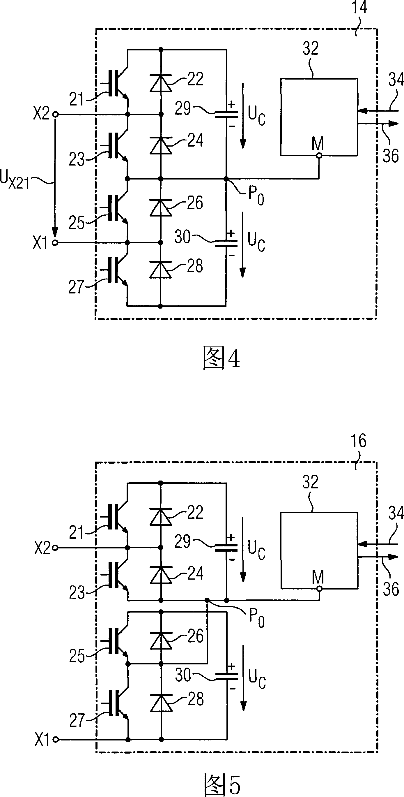
[0026] FIG. 4 is a detailed illustration of an equivalent circuit diagram of a first embodiment of the subsystem 14 of the present invention. This bipolar subsystem 14 of the present invention has four breakable semiconductor switches 21, 23, 25 and 27, four diodes 22, 24, 26 and 28, two unipolar capacitors 29 and 30 and an electronic device 32 (below Referred to as "electronic module 32"). Four switchable semiconductor switches 21, 23, 25 and 27 are connected in series with each other. Each switchable semiconductor switch 21, 23, 25 and 27 is connected in antiparallel with a diode 22, 24, 26 and 28 respectively. Each two switchable semiconductor switches 21 and 23 , 25 and 27 are connected in parallel with a unipolar capacitor 29 , 30 respectively. The unipolar capacitors 29, 30 of this subsystem 14 are either formed from one capacitor, or from a plurality of such capacitors with a total capacitance of C 0composed of capacitor banks. The connection point between the two s...


PUM


Abstract

The invention relates to a converter circuit comprising at least one phase module (100) having an upper and a lower converter valve (T1, ..., T6), wherein each converter valve (Tl, ..., T6) has at least one two-pole subsystem. According to the invention, each two-pole subsystem (14) has four semiconductor switches (21, 23, 25, 27), which can be switched off and are connected electrically in series, four diodes (22, 24, 26, 28), which are each connected electrically back-to-back in parallel with one semiconductor switch (21, 23, 25, 27) which can be switched off, two unipolar storage capacitors (29, 30), which are connected electrically in series and in parallel with the series circuit comprising the semiconductor switches (21, 23, 25, 27), and an electronic system (32), whose reference potential connection (M) is electrically conductively connected to a common potential (P0).; This results in a subsystem (14), at whose connection terminals (X2, Xl) it is possible to generate a terminal voltage (UX21) having four potential stages, which requires only one electronic system (32), whose energy supply takes place symmetrically, and which does not require any increased complexity in terms of potential isolation.

Description

technical field [0001] The invention relates to a converter circuit according to the preamble of claim 1 . Background technique [0002] This type of converter circuit is disclosed in DE 10103031 A1, and the equivalent circuit diagram of this converter circuit is shown in detail in FIG. 1 . As shown in this equivalent circuit diagram, the known converter circuit has three phase modules, each denoted by 100 . The DC voltage terminals of these phase modules 100 are respectively connected to the positive and negative DC voltage buses P 0 and N 0 Conductively connected. The two DC voltage buses P 0 and N 0 There is a DC voltage without a reference symbol between them. Each phase module 100 has an upper diverter valve T1 , T3 , T5 and a lower diverter valve T2 , T4 , T6 . Each of these variable flow valves T1 to T6 has a certain number of two-pole subsystems 11 connected in series. This equivalent circuit diagram illustrates four of the subsystems 11 . Instead of the two...

Claims


Application Information

Patent Timeline
Patent Type & Authority Applications(China)
IPC IPC(8): H02M5/45
CPCH02M7/217H02M7/25H02M7/4835
Inventor 马克·希勒
Owner SIEMENS AG
Why Eureka
Try Eureka