Piezoelectricity resonator

A resonator and piezoelectric technology, applied in the direction of piezoelectric devices/electrostrictive devices, electrical components, impedance networks, etc., can solve cracks, hinder the thinning of piezoelectric resonators with built-in capacitors, and the sealing substrate 103 is prone to cracks And other issues

Inactive Publication Date: 2008-08-27
KYOCERA CORP
View PDF1 Cites 5 Cited by
  • Summary
  • Abstract
  • Description
  • Claims
  • Application Information

AI Technical Summary

Problems solved by technology

However, in conventional piezoelectric resonators with built-in capacitors, the pair of sealing substrates 103 are made of a ceramic material. Therefore, when forming the flat-shaped sealing substrates 103 or assembling the piezoelectric resonators with built-in capacitors, there is a gap between the sealing substrates. Problems prone to cracks or cracks on 103
In particular, as the thickness of the sealing substrate 103 is reduced, the above-mentioned problems are more likely to occur. Therefore, there is a limit in producing the sealing substrate 103 with good yield, which hinders the thinning of the capacitance built-in piezoelectric resonator.

Method used


Image

  • Piezoelectricity resonator
  • Piezoelectricity resonator
  • Piezoelectricity resonator

Examples


Embodiment Construction

[0032] Hereinafter, the piezoelectric resonator of the present invention will be described in detail based on the drawings.

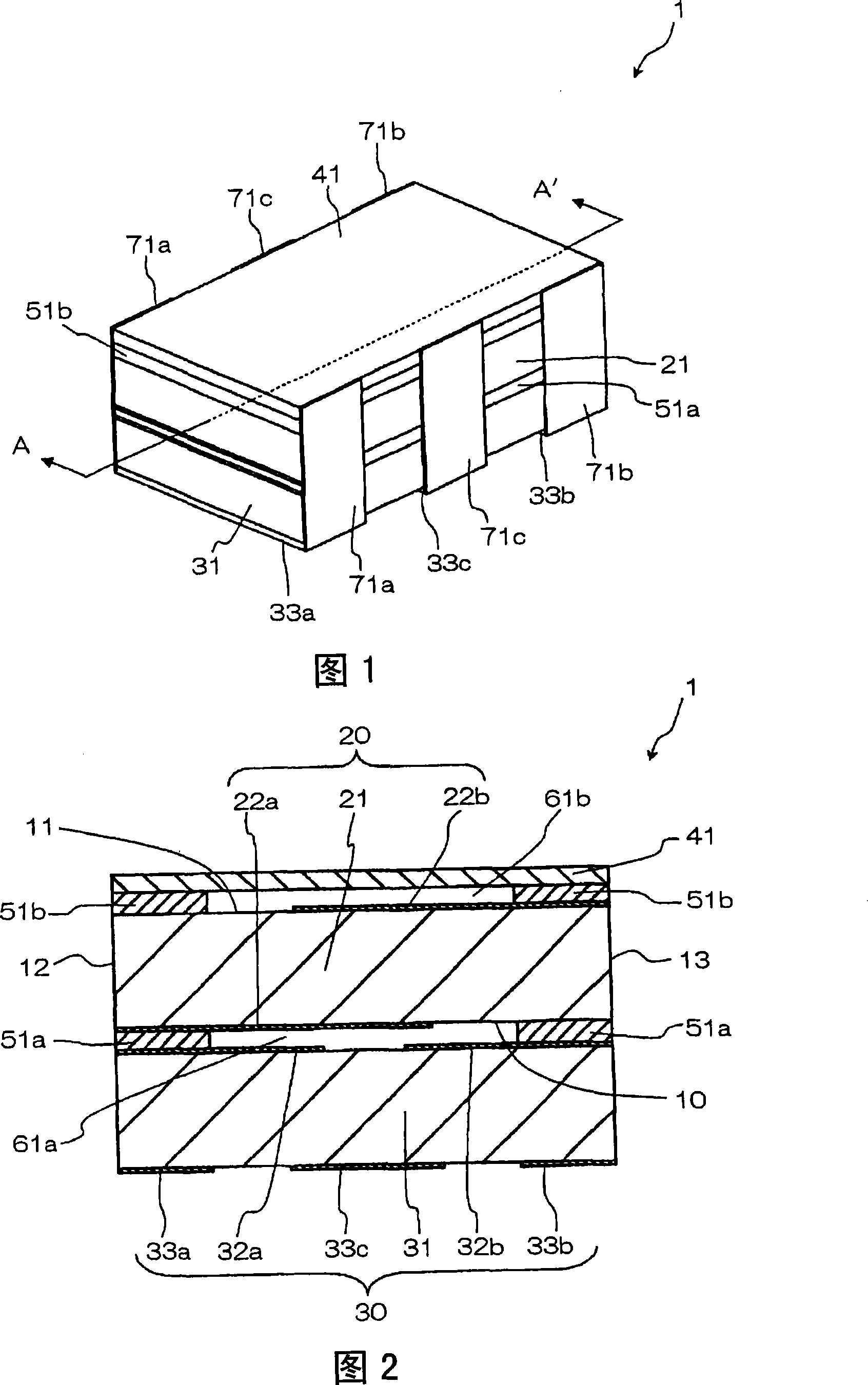
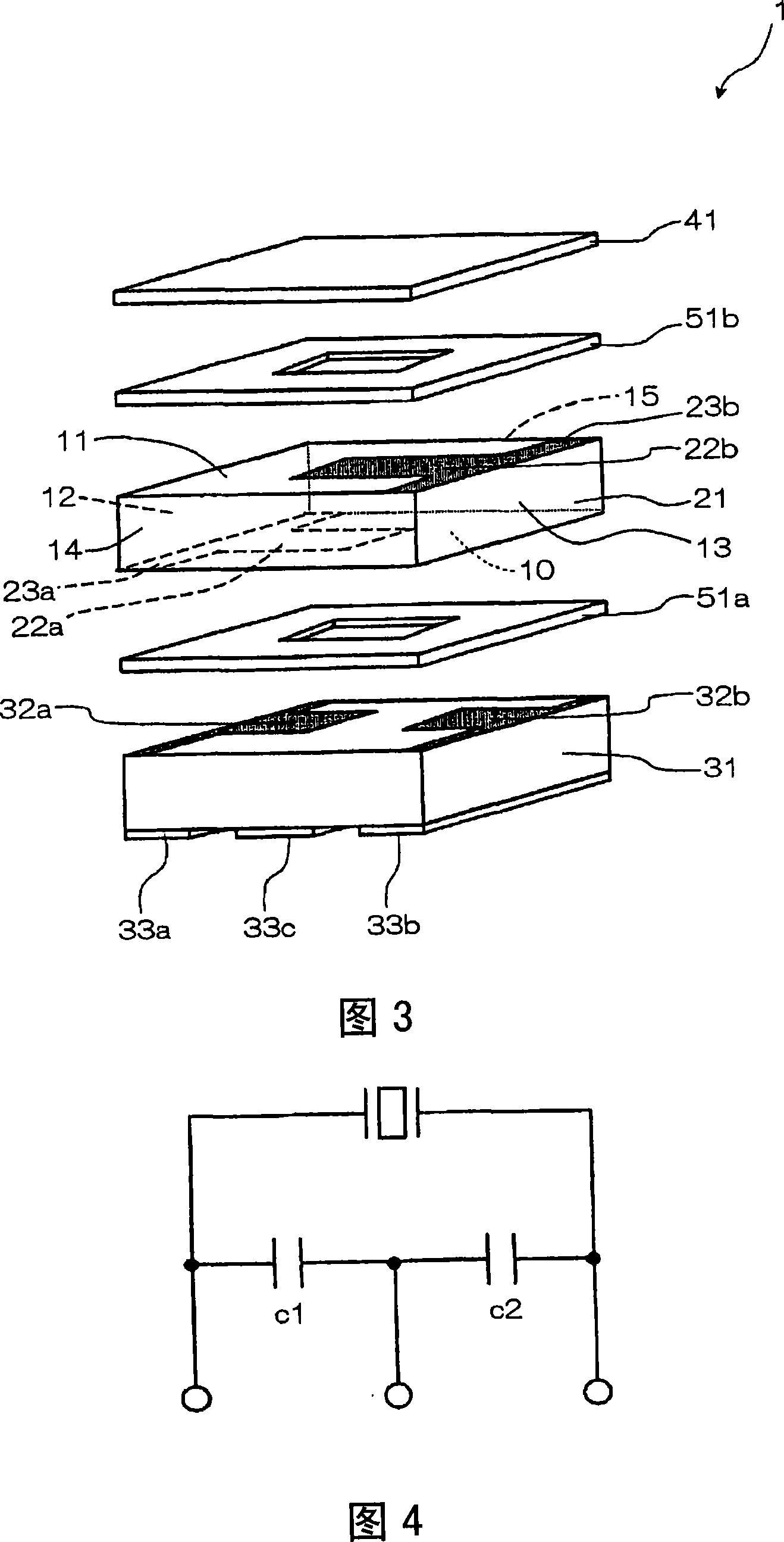
[0033] Fig. 1 is an external perspective view schematically showing an example of the piezoelectric resonator of the present invention, Fig. 2 is a sectional view taken along line A-A' of Fig. 1 , and Fig. 3 is an exploded perspective view.

[0034] In addition, in this embodiment, a piezoelectric resonator of a type incorporating an electrostatic capacitance will be described.

[0035] The piezoelectric resonator 1 shown in the figure mainly includes: a piezoelectric substrate 21 and two sealing substrates 31 , 41 . More specifically, as shown in FIG. 2 , the first sealing substrate 31 is bonded to the piezoelectric substrate 21 via the first frame body 51 a to form a first vibration space 61 a on the first main surface 10 side of the piezoelectric substrate 21 , and The second sealing substrate 41 is bonded to the piezoelectric substrate 21 via the s...


PUM

PropertyMeasurementUnit
thicknessaaaaaaaaaa
thicknessaaaaaaaaaa

Abstract

Disclosed is a thin and small-sized piezoelectric resonator with a built-in capacitor having excellent reliability. In this piezoelectric resonator, a pair of vibrating electrodes are formed on both major surfaces of a piezoelectric substrate, and a sealing substrate which is made of a ceramic material for forming an electric capacitor is joined onto one of the vibrating electrodes via a frame member while another sealing substrate made of a resin material is joined onto the other vibrating electrode via another frame member.

Description

technical field [0001] The present invention relates to piezoelectric resonators used in oscillation circuits, filter circuits, and the like. Background technique [0002] As a conventional piezoelectric resonator, for example, a capacitor built-in piezoelectric resonator shown in FIG. 8 is known (for example, refer to Patent Document 1). In the piezoelectric resonator with built-in capacitance shown in FIG. To seal the substrate 103 , ensure that the frame surrounds each vibrating electrode 102 . [0003] The piezoelectric substrate 101 is made of a piezoelectric ceramic material, and a piezoelectric resonance element is formed by providing vibrating electrodes 103 on both main surfaces. In addition, the sealing substrate 103 is made of a ceramic material, and forms an electrostatic capacity by electrodes provided on its upper and lower surfaces. Specifically, between the external terminal electrodes 109 and the internal electrodes 106 provided on the outer surface of th...

Claims


Application Information

Patent Timeline
Patent Type & Authority Applications(China)
IPC IPC(8): H03H9/02H03H9/17H01L41/09
CPCH03H9/177H03H9/0561
Inventor 古江纯司村桥昌人畑裕二
Owner KYOCERA CORP
Why Eureka
Try Eureka