Evacuating drum-type tank washer

A drum-type washing tank technology, which is applied to the processing of textile material containers, liquid/gas/steam fiber/sliver/roving processing, etc., can solve problems such as unreasonable structure of the washing tank, uneven rewashing of wool tops, etc., and achieve pumping The suction is uniform, the suction is good, and the effect of preventing the loss of suction

Inactive Publication Date: 2008-09-03
QINGDAO HICORP GROUP CO LTD
View PDF0 Cites 5 Cited by
  • Summary
  • Abstract
  • Description
  • Claims
  • Application Information

AI Technical Summary

Problems solved by technology

[0003] The invention aims at the unreasonable structure of the washing tank in the prior art and the defect of uneven rewashing of wool tops, and provides a suction drum type washing tank, which effectively solves the problem of uneven rewashing of wool tops

Method used


Image

  • Evacuating drum-type tank washer
  • Evacuating drum-type tank washer
  • Evacuating drum-type tank washer

Examples


Embodiment Construction

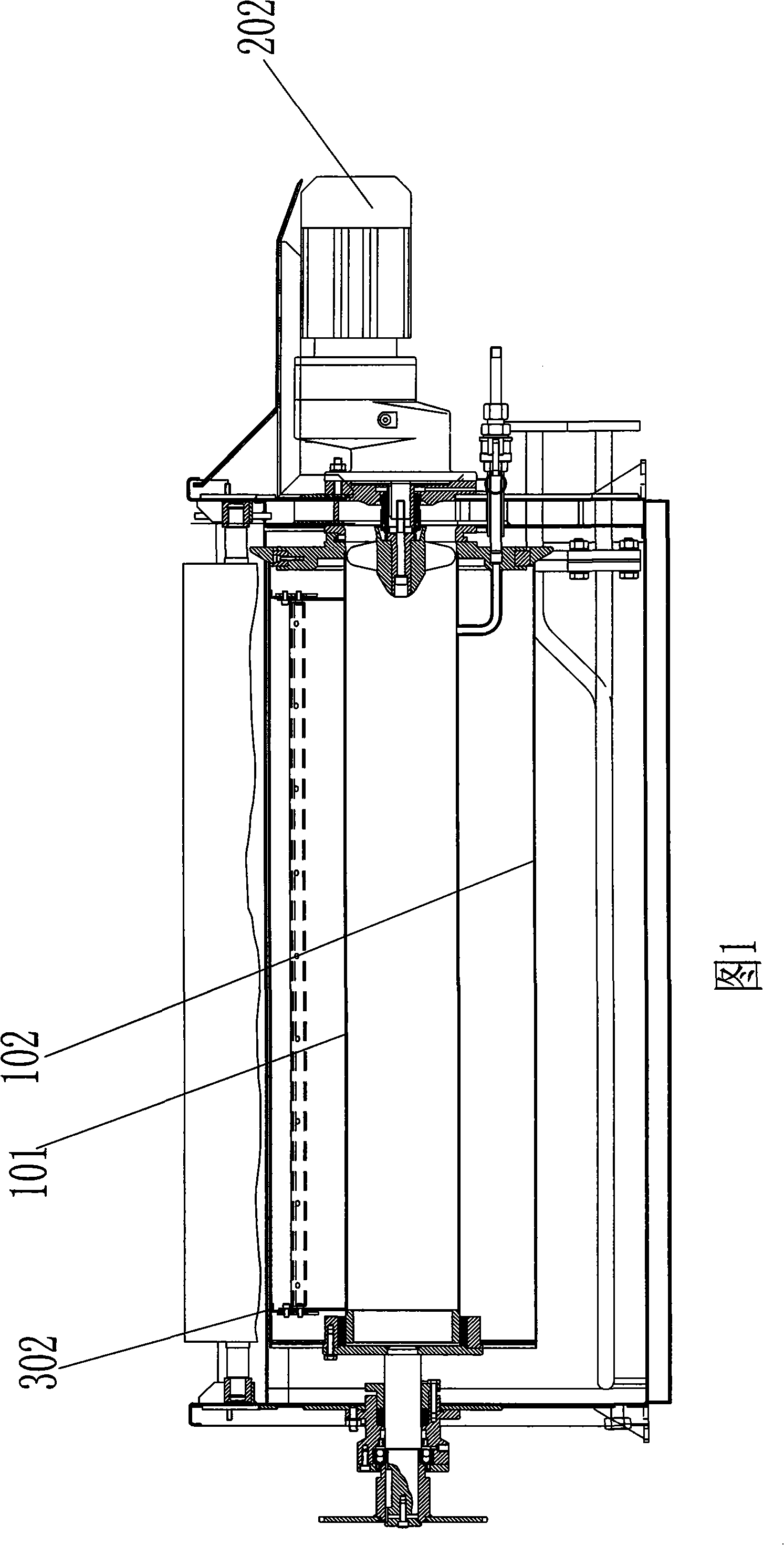
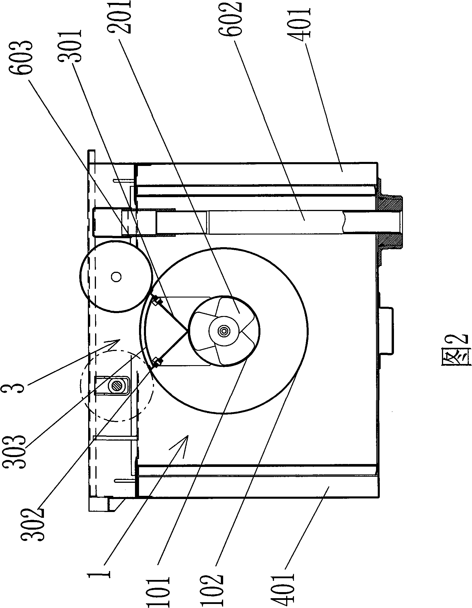
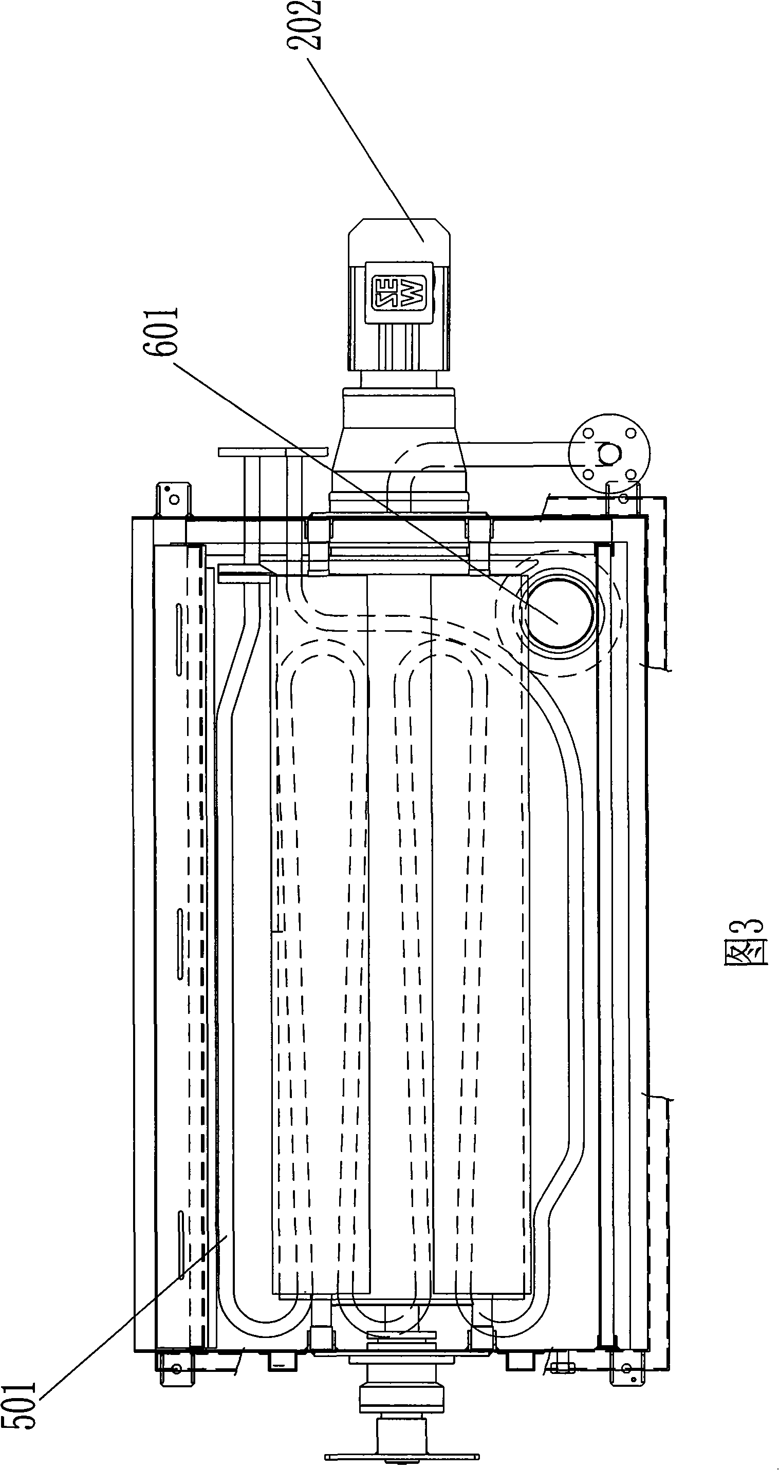
[0022] Combined with Figure 1, Figure 2 and Figure 3, the suction drum type washing tank includes: suction device and drum 1, drum 1 has an inner cylinder 101 and an outer cylinder 102, flanges are installed at both ends of the outer cylinder 102, and linings are installed inside The inner cylinder 101 cooperates with the outer cylinder 102 through the bushing, the inner cylinder 101 is fixed, and the outer cylinder 102 can rotate around the inner cylinder 101 under the action of the transmission drive device. The suction device includes a propeller 201 and a gear motor 202. The propeller 201 is installed at the liquid outlet of the inner tube 101 , and the rotating shaft of the reduction motor 202 is connected with the propeller 201 . Both the above-mentioned inner cylinder 101 and outer cylinder 102 are provided with ventilation holes, and the ventilation holes on the inner cylinder 101 are gradually denser from one end close to the suction device to the other end, and the ve...


PUM


Abstract

The invention discloses a suction roller type tank washer, comprising: a suction device and a roller; the roller includes an inner roller and an outer roller, two ends of the outer roller is installed with a flange disc which is installed with a lining inside, the inner roller is cooperated with the outer roller; the outer roller can surround the immovable inner roller to rotate, the suction device comprises an airscrew and a deceleration electric engine, the airscrew is installed on a liquid outlet of the inner roller, the rotating shaft of the deceleration electric engine is connected with the airscrew. Both the inner roller and the outer roller are provided with ventholes; the ventholes on the inner roller are gradually dense from one end near the suction device to the other end, the ventholes on the outer roller are uniformly arrayed. Such structure leads to sparser distribution of the ventholes on the surface of the inner roller where the suction force is larger, and leads to denser distribution of ventholes at the position where the suction force is smaller so that the suction force on the outer roller is uniform and consistent, thus solving the problem about asymmetry of wool tops backwashing.

Description

technical field [0001] The invention relates to a wool spinning rewashing machine, in particular to a washing tank part of the rewashing machine. Background technique [0002] At present, the rewashing machine used in the textile industry has a washing tank comprising: a drum and a suction pump, the drum is uniformly provided with air holes, and the suction pump is fixed on one side of the drum. This kind of structure produces uneven suction on the surface of the drum. The surface of the drum near the suction pump has a large suction, and the surface of the drum far away from the suction pump has a small suction, resulting in uneven rewashing of wool tops. There is no area where wool tops are entangled on the drum, and there is no sealing device at the corresponding position inside the drum, resulting in waste of suction and poor penetrating power of washing liquid through wool tops. Contents of the invention [0003] Aiming at the unreasonable structure of the washing ta...

Claims


Application Information

Patent Timeline
Patent Type & Authority Applications(China)
IPC IPC(8): D06B23/14D06B3/02
Inventor 孙旭赵传福郭加阳
Owner QINGDAO HICORP GROUP CO LTD
Why Eureka
Try Eureka