Rectangle plane net shell structure and rectangle plane string supporting dome

A technique of suspending domes and planar nets, which is applied to arched structures, dome structures, roofs, etc., and can solve problems such as inability to meet architectural functions and novel and diverse architectural shapes.

Inactive Publication Date: 2008-09-03
HENAN UNIVERSITY
View PDF0 Cites 12 Cited by
  • Summary
  • Abstract
  • Description
  • Claims
  • Application Information

AI Technical Summary

Problems solved by technology

[0005] In practice, the single-layer reticulated shell suspensive dome is widely used in buildings with circular or elliptical planes, but it is not suitable for large-span buildings with rectangular planes. The support dome structure also cannot meet the growing demand for novel and diverse architectural functions and architectural shapes.

Method used


Image

  • Rectangle plane net shell structure and rectangle plane string supporting dome
  • Rectangle plane net shell structure and rectangle plane string supporting dome
  • Rectangle plane net shell structure and rectangle plane string supporting dome

Examples


Embodiment Construction

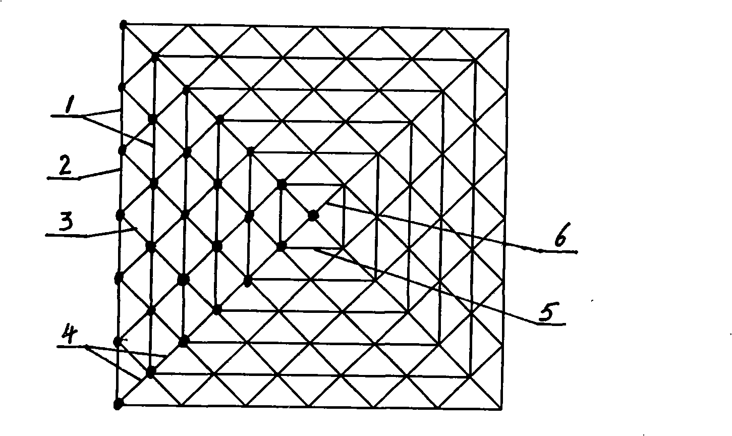
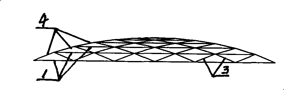
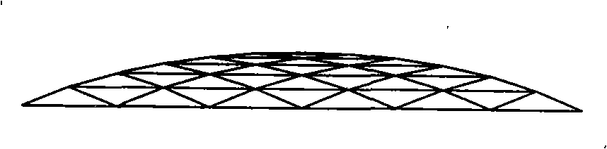
[0035] Figure 1-Figure 4 The shown rectangular planar reticulated shell structure includes a group of similar rectangular ring beams 1 whose center is on a vertical line and which are sequentially arranged at random heights and whose diagonal lines increase successively. Each rectangular ring beam is composed of a ring The direction rods 2 are connected end to end in turn, and the vertices of the same phase of two adjacent rectangular ring beams are connected with the vertex connecting rod 4, and the side connecting rods 3 are arranged between the beam sides of the adjacent rectangular ring beams, and the side connecting rods 3 are arranged between the sides. The two ends of the connecting rod 3 are respectively rigidly connected to the joints of the ring rod 2 in the adjacent beam side; the rectangular ring beam 5 located in the center of the reticulated shell is diagonally provided with two central connecting rods 6, and two central connecting rods 6 The central node is for...


PUM


Abstract

The present invention relates to a rectangular planar lattice shell structure which comprises a group of similar rectangular ring girders which have centers in one vertical line and are high-and-low distributed in sequence and have diagonals that enlarges gradually. Each rectangular ring girder is obtained by connecting from ring to rod in sequence. A peak connecting rod is provided between the peaks of adjacent rectangular ring grid. An edge connecting rod is provided between the edges of the grid. Two ends of the edge connecting rod are respectively connected with the node of the adjacent girder-side circumferential rod. The opposite positions of rectangular ring girder at the center are provided with two central connecting rods. The connecting rods form a central node at the intersection. The rectangular plane suspend-dome is added with a stretching supporting structure on the base of the lattice shell. The rectangular ring bracing cable is corresponding with the rectangular ring girder. The diagonal bracing cable is arranged in the vertical plane which the diagonal corresponding with the lattice shell is located in. Two ends of the diagonal bracing cable are connected with the peak of the rectangular ring girder at the margin. The place between the intersection of the diagonal bracing cables and the corresponding node of the lattice shell and the place between the intersection of two bracing cables and the corresponding node of the lattice shell are respectively provided with a brace rod. When a pre-stress is exerted in the bracing cable, the lattice shell and the stretching supporting structure form a whole force-bearing structure.

Description

technical field [0001] The present invention relates to a roof structure of a large-span building, especially a reticulated shell structure and a hybrid space structure formed by introducing two components of cables and struts on the basis of the reticulated shell structure and combining them in a specific way—— Suspension dome. Background technique [0002] With the gradual increase of long-span buildings and the gradual increase of their span and scale, many new spatial structure forms have emerged on the roof of long-span buildings. Among them, the single-layer reticulated shell structure is due to its beautiful structure, simple construction and It can be popularized due to the advantages of reasonable force. The structural forms of single-layer reticulated shells that have been proposed so far include single-layer spherical reticulated shells, single-layer cylindrical reticulated shells, single-layer ellipsoidal reticulated shells, single-layer rotating parabolic retic...

Claims


Application Information

Patent Timeline
Patent Type & Authority Applications(China)
IPC IPC(8): E04B7/00E04B7/08E04B1/342E04B1/32E04B7/14
Inventor 杜文风刘国光范博
Owner HENAN UNIVERSITY
Why Eureka
Try Eureka