Gas-liquid separator for heat pump scavenging oil using siphon mode

A gas-liquid separator, heat pump technology, used in heat pumps, refrigeration and liquefaction, lighting and heating equipment, etc., can solve the problem of lubricating oil entering, increase service life, prevent liquid shock, improve reliability and refrigeration heating the effect of the ability

Inactive Publication Date: 2008-09-03
SUZHOU HALDANE NEW ENERGY
View PDF0 Cites 11 Cited by
  • Summary
  • Abstract
  • Description
  • Claims
  • Application Information

AI Technical Summary

Problems solved by technology

Most of the current gas-liquid separator technology uses centrifugal separation to separate gas and liquid, but it does not allow a small amount of lubricating oil in the liquid to enter the compressor

Method used


Image

  • Gas-liquid separator for heat pump scavenging oil using siphon mode
  • Gas-liquid separator for heat pump scavenging oil using siphon mode

Examples


Embodiment Construction

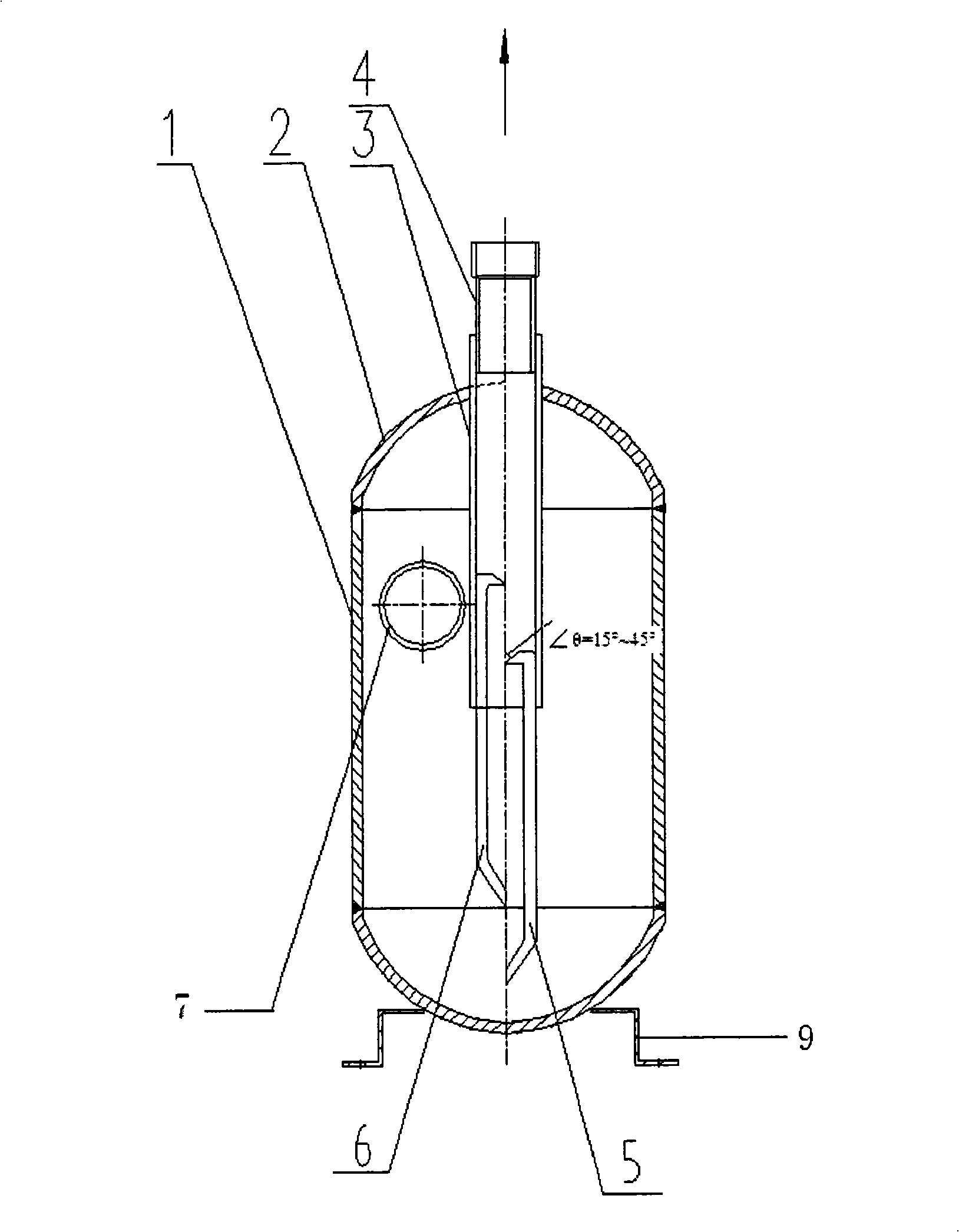
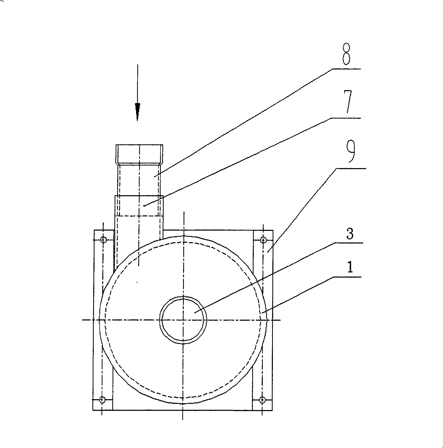
[0014] refer to figure 1 , figure 2 As shown, the cylinder body 1 made of seamless steel pipe in the present invention has a head 2 on the upper part, and a gas return sleeve 3 is installed inside the center of the cylinder body 1, and a gaseous refrigerant gas return pipe in a vertical direction is connected to the upper part of the gas return sleeve 3 4. The tangential direction of the middle part of the cylinder body 1 is welded with an air intake sleeve 7, the air intake sleeve 7 is connected to the intake pipe 8, the bottom of the cylinder body 1 is welded with a base 9, and the inner wall of the return air sleeve 3 is welded with a low oil return pipe 5 and a high position The oil return pipe 6, the low oil return pipe 5 and the high oil return pipe 6 pipe ends all stretch out from the lower opening of the inner wall, and the low oil return pipe 5 is lower than the high oil return pipe 6 about 1 / 5~1 / 4 of the pipe length. The position of the air intake pipe 8 is higher ...


PUM


Abstract

The invention discloses a siphon type gas-liquid separator used for a heat pump, comprising a barrel made of a seamless steal tube, a closing end disposed at the upper portion thereor, a gas return bushing disposed in the internal portion of the barrel center, a vertical gaseous refrigerant gas return tube connected at the upper portion of the gas return bushing, a gas feeding bushing welded in the tangential direction of the barrel, a gas feeding tube connected with the gas feeding bushing, a base welded at the bottom of the barrel, and a low level oil return tube and a high level oil return tube both welded on the internal wall of the gas return bushing. The terminals of both the low level oil return tube and the high level oil return tube extend outside the lower opening of the internal wall. The inventive gas-liquid separator can not only prevent compressor liquid hammer, but also let the lubricant oil carried by the refrigerant enter the compressor to depress gas discharge temperature of the compressor, increase service life of the compressor, and enhance reliability of the system and ability for refrigeration and heating.

Description

technical field [0001] The invention relates to a gas-liquid separator for a heat pump system, in particular to a gas-liquid separator for a heat pump which adopts a siphon way to return oil. Background technique [0002] Currently, existing heat pump systems include a compressor, a four-way valve, a condenser, an expansion valve, and an evaporator. In the refrigeration process, the gaseous refrigerant pressurized by the compressor enters the air-side heat exchanger through the four-way valve to exchange heat, then cools down, and then depressurizes through the expansion valve to become a low-temperature and low-pressure liquid, and then enters the water-side heat exchanger to evaporate Then it becomes a low-pressure gas and is sucked into the compressor through the four-way valve. During the heating process, the gaseous refrigerant pressurized by the compressor enters the water-side heat exchanger through the four-way valve to release heat and then cools down, so that the ...

Claims


Application Information

Patent Timeline
Patent Type & Authority Applications(China)
IPC IPC(8): F25B30/02F25B43/00
Inventor 曹锋王凯邢子文束鹏程
Owner SUZHOU HALDANE NEW ENERGY
Why Eureka
Try Eureka