Large temperature rise compression heat pump units

A compression heat pump and compressor technology, applied in heat pumps, refrigerators, refrigeration components, etc., can solve problems such as the reduction of cold water outlet temperature, the reduction of system performance coefficient, and the reduction of energy utilization efficiency, so as to reduce heat transfer temperature difference, The effect of improving the coefficient of performance and reducing the temperature difference

Inactive Publication Date: 2008-09-03
TSINGHUA UNIV +1
View PDF0 Cites 14 Cited by
  • Summary
  • Abstract
  • Description
  • Claims
  • Application Information

AI Technical Summary

Problems solved by technology

For commonly used heat pump devices, the "large temperature difference, small flow" operation mode usually adopted will cause an increase in the temperature of the hot water supply and a decrease in the temperature of the cold water outlet when the inlet water temperature is constant, resulting in an increase in the condensation pressure. And the reduction of evaporation pressure leads to the reduction of system performance coefficient (COP) and the reduction of energy utilization efficiency

Method used


Image

  • Large temperature rise compression heat pump units
  • Large temperature rise compression heat pump units
  • Large temperature rise compression heat pump units

Examples


Embodiment 1

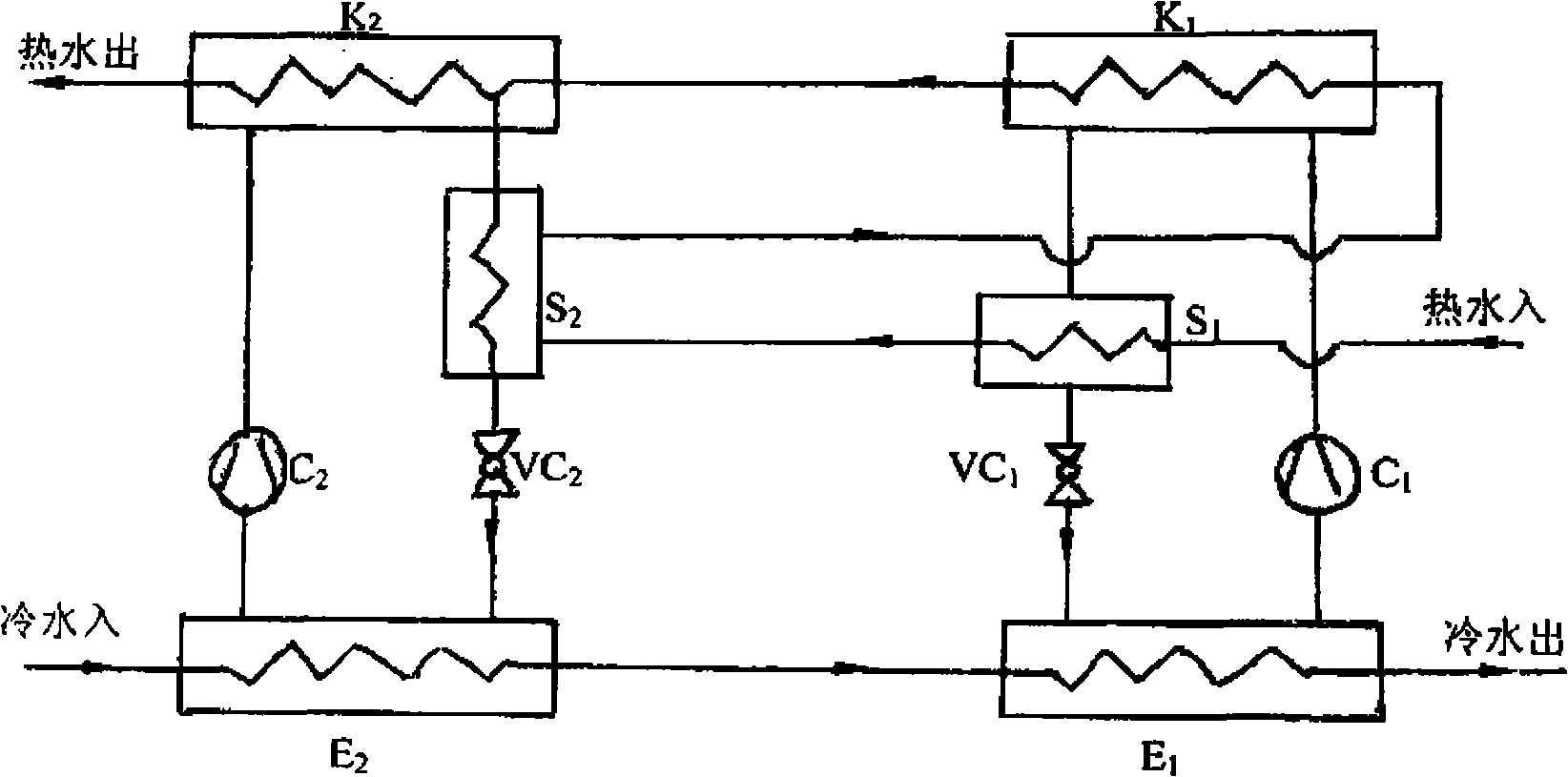
[0013] Embodiment 1 Two-stage series-connected compression heat pump unit with subcooling

[0014] As shown in Figure 1(a), the compressor C1 is connected between the first-stage condenser K1 and the evaporator E1, and the subcooler S1 and the throttling device VC1 are connected in parallel with the compressor C1 after being connected in series, and the second-stage condenser K2 The compressor C2 is connected with the evaporator E2, and the subcooler S2 and the throttling device VC2 are connected in parallel with the compressor C2 after being connected in series; 40 ℃ hot water return water enters the subcooler S1 from the hot water inlet of the subcooler S1, It flows through the cooler S1, the subcooler S2, the condenser K1 and the condenser K2 in sequence, and after being heated by the two-stage condenser, the high temperature hot water is output from the hot water outlet of the condenser K2, and the temperature of the hot water is 50-55°C. The return water of 25°C cold wate...

Embodiment 2

[0015] Embodiment 2 Compression heat pump unit with two stages in series and subcooling

[0016] As shown in Figure 1(b), the basic structure of the heat pump unit is the same as that of Embodiment 1, the difference is that the hot water pipeline is a subcooler S1, a subcooler S2, and the first stage condenser K1 are connected in parallel and then connected to the second The stage condenser K2 is connected in series. The return water of 40°C hot water passes through the parallel circuit of subcooler S1, subcooler S2, and first-stage condenser K1, and then passes through the second-stage condenser K2. After heating, it outputs hot water with a higher temperature. At 50-55°C. The return water of 25°C cold water flows through evaporator E2 and evaporator E1 successively, and then the temperature is lowered step by step, and then 10°C cold water is output. The hot water is heated up in steps, and the cold water is cooled in steps in the two-stage evaporator. The condensation pre...

Embodiment 3

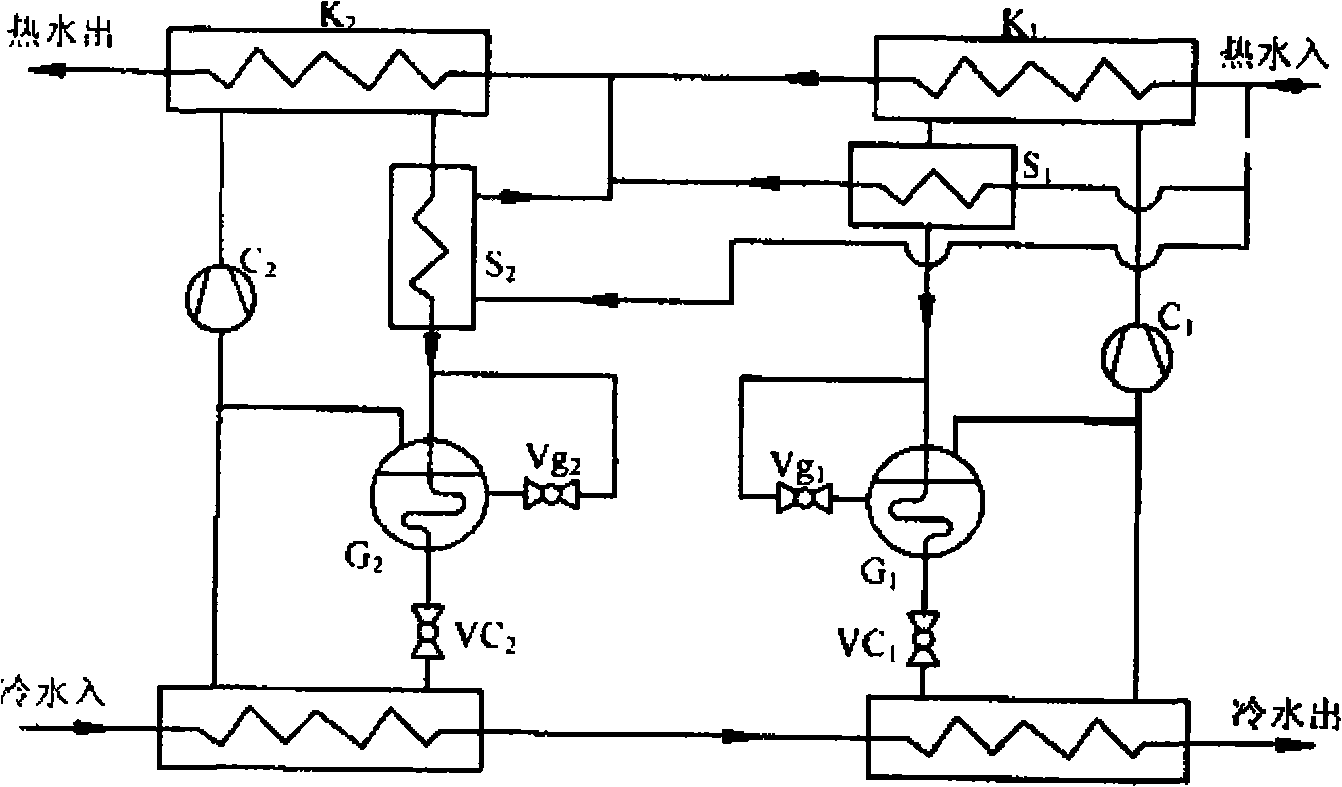
[0017] Embodiment 3 Two-stage series connection plus subcooling and economizer compression heat pump unit

[0018] In order to further improve the coefficient of performance of the compression heat pump unit, such as figure 2 As shown, the heat pump unit is composed of two heat pump units, and its basic structure is the same as that of Embodiment 2, the difference is that an economizer G1 is connected in series between the subcooler S1 and the throttling device VC1; An economizer G2 is connected in series between the throttling device VC2. The return water of 40°C hot water passes through the parallel circuit of subcooler S1, subcooler S2, and first-stage condenser K1, and then passes through the second-stage condenser K2 After being heated, it outputs hot water with a higher temperature, and the temperature of the hot water is 50-55°C. The return water of 25°C cold water flows through evaporator E2 and evaporator E1 successively, and then the temperature is lowered step by s...


PUM


Abstract

The invention pertains to heating and hot water supply field, relating to a high efficiency large temperature rise compression heat pump set with a big inlet-outlet temperature difference at both a heat sink side and a head source side. The large temperature rise compression heat pump set is configured by assembling two water source heat pump devices, and each heat pump set comprises separately in series or in parallel a compressor, a condenser, an evaporator, a subcooler, and a throttling device, or an added economizer, and forms a separate working medium circulation loop. The inventive large temperature rise compression heat pump set can heat returned hot water step by step from a low temperature to a high temperature, the cold water is cooled step by step in a reverse direction of the temperature rise of the cooling water, and temperature difference between the hot water and cold water at the inlet and outlet of the heat pump is enlarged; and the performance coefficient of the heat pump set is further enhanced comparing with a simple two-stage compression heat pump in series, so that the comprehensive energy utilization efficiency and economy of the inventive system are increased greatly comparing with a common heat pump set.

Description

technical field [0001] The invention belongs to heating and hot water supply devices, in particular to a high-efficiency large-temperature-rise compression heat pump unit capable of obtaining relatively large inlet and outlet temperature differences at both the cold and heat source sides. Background technique [0002] With the maturity of heat pump technology, various heat pump technologies using groundwater, surface water or industrial waste water as low-temperature heat sources have been widely used in various heating and hot water supply systems. The coefficient of performance of the heat pump unit is an important factor in determining the efficiency of energy utilization. For commonly used heat pump devices, the "large temperature difference, small flow" operation mode usually adopted will cause an increase in the temperature of the hot water supply and a decrease in the temperature of the cold water outlet when the inlet water temperature is constant, resulting in an in...

Claims


Application Information

Patent Timeline
Patent Type & Authority Applications(China)
IPC IPC(8): F25B30/06
Inventor 付林张世钢武姿陈闯
Owner TSINGHUA UNIV
Why Eureka
Try Eureka