Device for separating a gas-liquid mixture

A gas-liquid mixture and separation device technology, applied in separation methods, dispersed particle separation, chemical/physical processes, etc., can solve problems such as poor separation efficiency and achieve the effect of improving fluid separation

Active Publication Date: 2008-09-03
MAHLE INT GMBH
View PDF1 Cites 21 Cited by
  • Summary
  • Abstract
  • Description
  • Claims
  • Application Information

AI Technical Summary

Problems solved by technology

In the process of separating gas-liquid mixtures with low flows in enterprises, the separation efficiency achieved by this existing separation device is particularly poor.

Method used


Image

  • Device for separating a gas-liquid mixture
  • Device for separating a gas-liquid mixture
  • Device for separating a gas-liquid mixture

Examples


Embodiment Construction
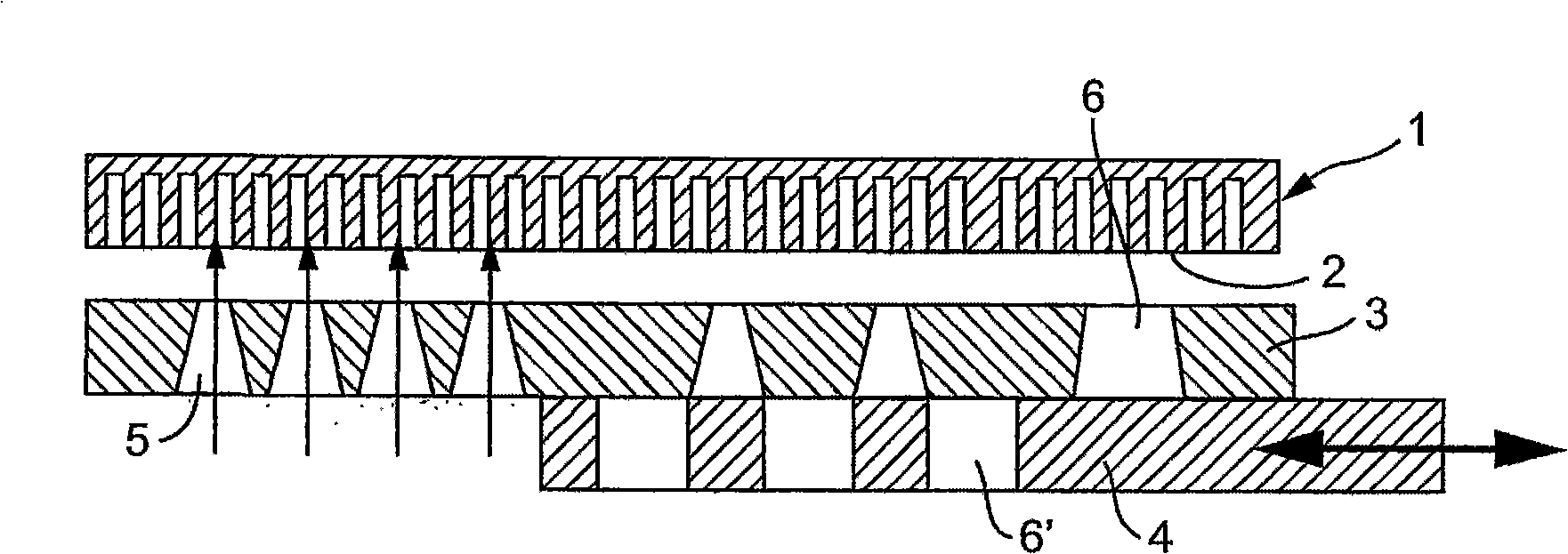
[0023] figure 1

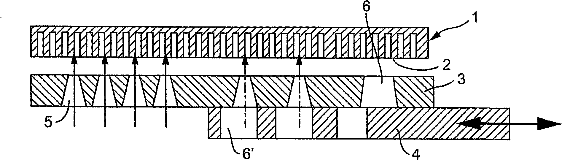
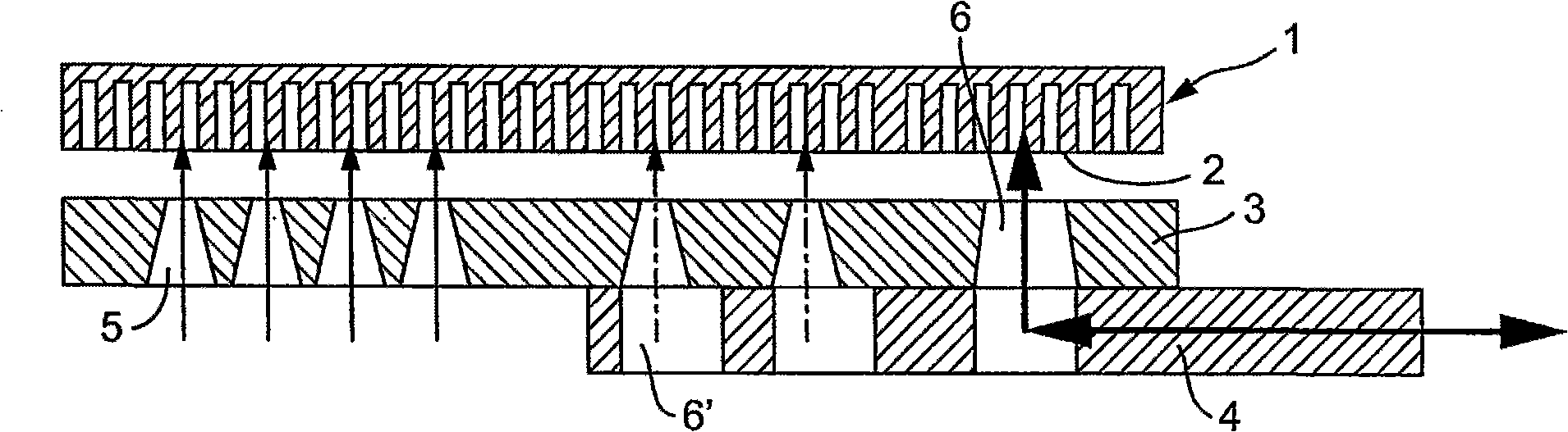
[0024] In the embodiment shown in FIG. 1, a separating device comprises an impact element 1 of plate-like construction. The percussion element has a percussion surface which can be fed through the grid-like arrangement of partitions 2 .

[0025] Close to the percussion element 1 is a device consisting of a connecting rod 3 and a slide valve 4 associated therewith. The connecting rod 3 comprises first and second acceleration openings 5 ​​and 6 . Opening 6 ' on the spool valve 4 cooperates with the second acceleration opening 6. With the movement of the spool valve 4, the acceleration opening 6 on the connecting rod 3 is closed or opened. In the open state of the second accelerating opening 6, the opening 6' on the slide valve makes the flow through cross section of the second accelerating opening 6 completely or partially unblocked. The openings 6' are arranged on the spool valve 4 in such a way that when the position of the spool changes, a part of the se...


PUM


Abstract

The invention relates to a device for separating a gas-liquid mixture, in which the liquid portion exists in the form of small particles, especially for ventilating a crankcase of an internal combustion engine, by separating and coagulating the liquid particles on a target area. The liquid mixture, after acceleration in acceleration openings provided for this purpose, impacts the target area at an approximately right angle. The aim of the invention is to improve the aforementioned device in such a manner that it allows as high a degree of separation as possible for different sized volume flows of mixtures. For this purpose, the number and / or the cross-sections of the acceleration openings (5, 6) is varied, depending on the volume flow of mixtures, between a small complete cross-section for a low volume flow and a large complete cross-section for a large volume flow.

Description

technical field [0001] The invention relates to a device for separating gas-liquid mixtures, in particular during crankcase ventilation of internal combustion engines. Background technique [0002] One such separation device is disclosed in US Pat. No. 6,290,738 B1. In the separation device disclosed, the mixture flows through each acceleration opening at the same speed each time, in such a way that it does not depend on the total flow of the mixture fluid. The stated velocities appear lower at lower total flow rates and correspondingly higher at higher total flow rates. Since the separation efficiency will vary due to different impact velocities, the efficiency of this separation action will vary according to the existing mixture flow rate limited by the conditions of the enterprise. In the separation process of gas-liquid mixture with low flow rate in enterprises, the separation efficiency obtained by this existing separation device is particularly poor. Contents of th...

Claims


Application Information

Patent Timeline
Patent Type & Authority Applications(China)
IPC IPC(8): B01D45/08F01M13/04
CPCB01D45/08Y10S55/19F01M2013/0433F01M2013/045Y10S55/14F01M13/04
Inventor 罗伯特·东舍安德烈亚斯·恩德瑞克莱塞克·格利希斯特凡·鲁佩尔雅库普·厄兹卡亚
Owner MAHLE INT GMBH
Why Eureka
Try Eureka