Discharge lamp drive control circuit
A technology for driving control circuits and discharge lamps, applied in emergency protection circuit devices, electric light sources, electrical components, etc., can solve problems such as fire, disconnection of discharge lamps, poor connection between discharge lamps and connectors, etc.
- Summary
- Abstract
- Description
- Claims
- Application Information
AI Technical Summary
Problems solved by technology
Method used
Image

Examples
Embodiment approach 1
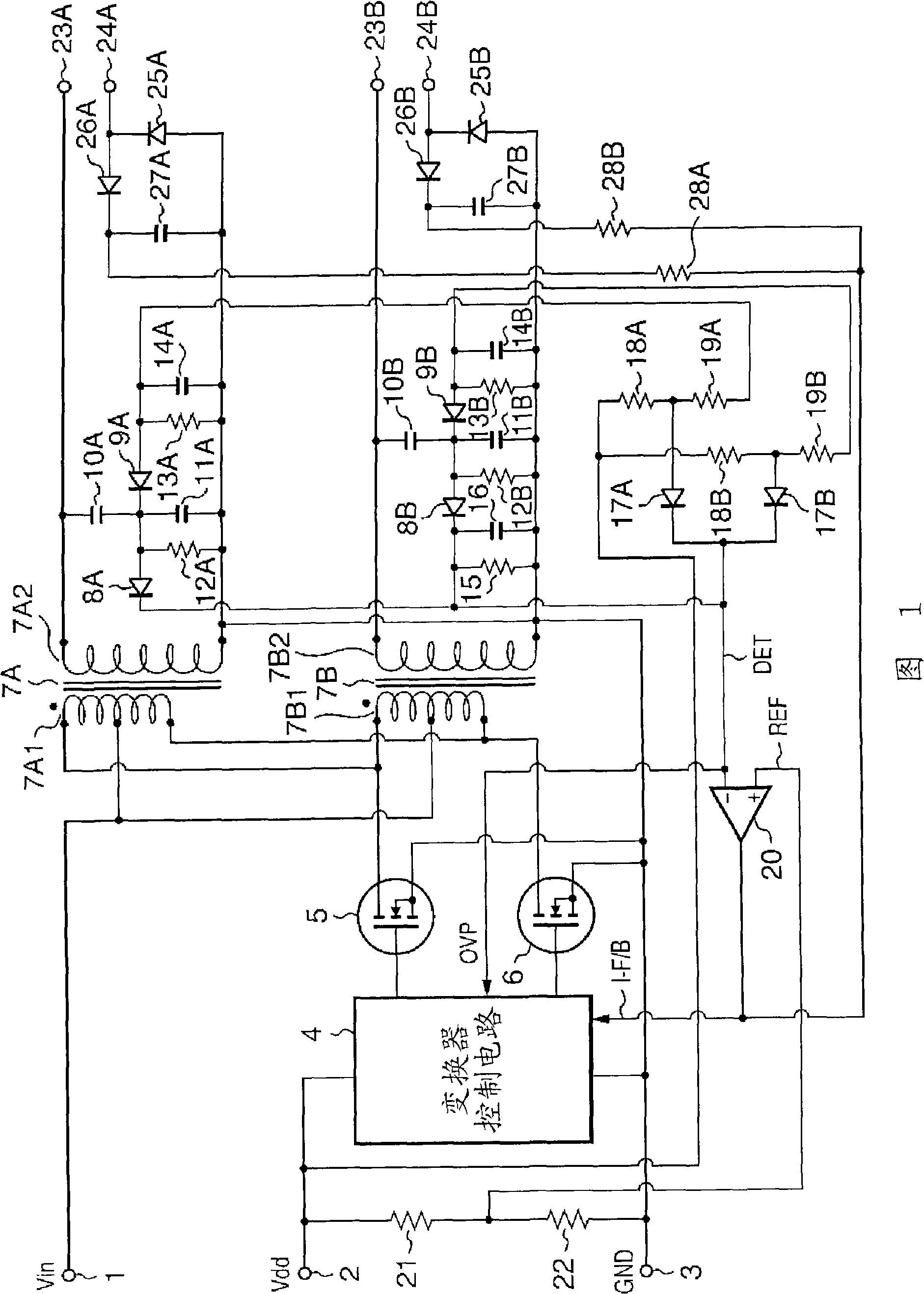
[0028] FIG. 1 shows a first embodiment of the present invention. In the discharge lamp drive control circuit shown in FIG. 1, two discharge lamps (not shown) are connected. In the discharge lamp driving control circuit shown in FIG. 1, the DC power supply voltage Vin supplied between the terminal 1 and the terminal 3 is composed of a converter control circuit 4, a pair of switching transistors 5 and 6, and a pair of driving transformers 7A and 7B. The converter is converted into a high-frequency driving voltage. The converted high-frequency driving voltage is respectively provided to the first discharge lamp (not shown) connected to the high-voltage side output terminal 23A, the low-voltage side output terminal 24A, and the low-voltage side output lamp connected to the high-voltage side output terminal 23B. These first and second discharge lamps are driven by a second discharge lamp (not shown) on terminal 24B.
[0029] In addition, the terminal 3 is a ground terminal, and is...
Embodiment approach 2
[0050] FIG. 3 shows a second embodiment of the present application, showing an example in which a voltage corresponding to a current flowing through a discharge lamp is detected on the driving transformer side. In FIG. 3, the DC power supply voltage Vin supplied between the terminal 30 and the terminal 32 is converted into a high-frequency driving voltage by an inverter composed of an inverter control circuit 33, a switching circuit 34 including semiconductor switching elements, and a driving transformer 35. . The converted high-frequency drive voltage is supplied to a discharge lamp (not shown) connected to the high-voltage side output terminal 36 and the low-voltage side output terminal 37 to light the discharge lamp. In addition, the terminal 32 is a ground terminal, and is supplied with a ground potential GND.
[0051] In addition, a DC operating voltage Vdd for operating the inverter control circuit 33 is supplied from the terminal 31 . A switch control signal for contr...
Embodiment approach 3
[0059] FIG. 4 shows a third embodiment of the present application. This third embodiment is a modified example of the second embodiment of the present application described in FIG. 3 , and the same reference numerals are assigned to the same parts as those in the second embodiment of the present application, and description thereof will be omitted. In the second embodiment of the present application shown in FIG. 3 , in the case of detecting the voltage corresponding to the driving current of the discharge lamp, detection is performed from the low voltage side of the secondary coil of the driving transformer 35 using a diode 51 and a resistor 52. .
[0060] In contrast, in the third embodiment shown in FIG. 4 , diodes 55 and 56 and a capacitor 57 are provided on the low voltage side output terminal 37 connected to the discharge lamp to detect a voltage corresponding to the drive current of the discharge lamp. This detection method has the same circuit configuration as the det...
PUM
 Abstract
Description
Claims
Application Information
 - Generate Ideas
- Intellectual Property
- Life Sciences
- Materials
- Tech Scout
- Unparalleled Data Quality
- Higher Quality Content
- 60% Fewer Hallucinations
Browse by: Latest US Patents, China's latest patents, Technical Efficacy Thesaurus, Application Domain, Technology Topic, Popular Technical Reports.
© 2025 PatSnap. All rights reserved.Legal|Privacy policy|Modern Slavery Act Transparency Statement|Sitemap|About US| Contact US: help@patsnap.com