Bolting machine

A technology of screwing and cylinders, applied in power tools, portable mobile devices, manufacturing tools, etc., can solve problems such as reducing exhaust efficiency, and achieve the effect of large exhaust flow and high exhaust efficiency

Inactive Publication Date: 2008-09-10
MAKITA CORP
View PDF2 Cites 3 Cited by
  • Summary
  • Abstract
  • Description
  • Claims
  • Application Information

AI Technical Summary

Problems solved by technology

[0007] However, according to the above-mentioned conventional suction flow switching mechanism, in the state where the suction flow is reduced to the small flow side in order to beat the wood, the exhaust flow when the piston moves up is also in a state of being reduced, so There will be a problem of reduced exhaust efficiency

Method used


Image

  • Bolting machine
  • Bolting machine
  • Bolting machine

Examples


Embodiment Construction

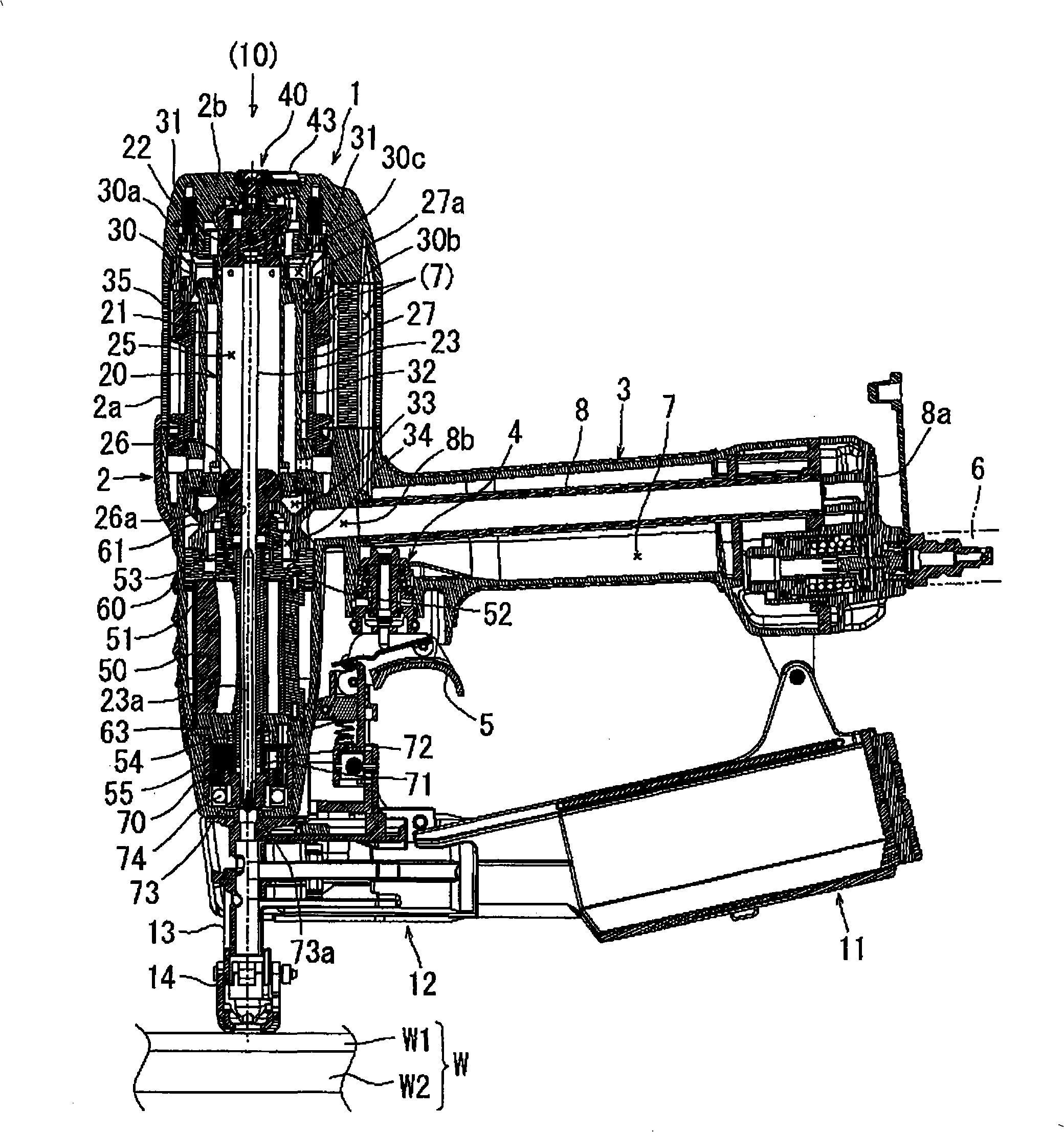
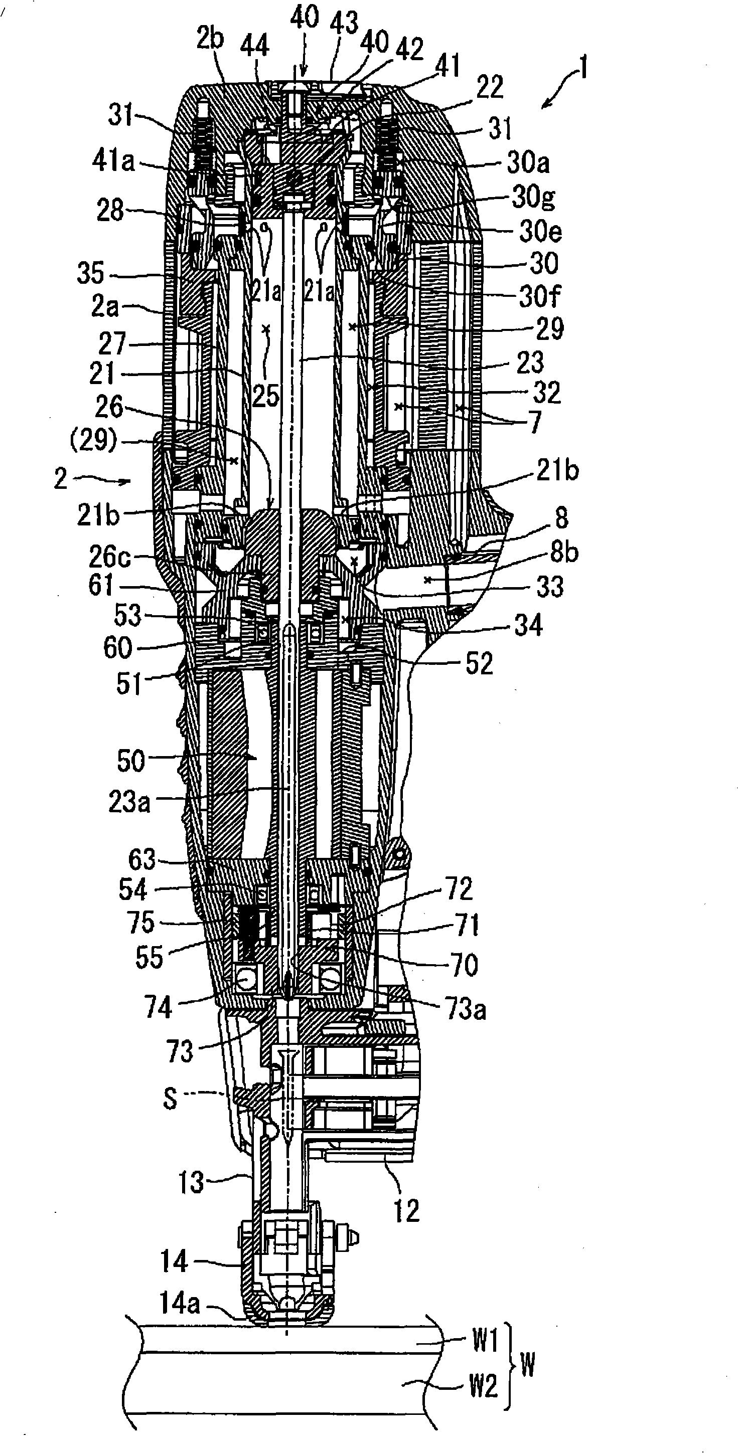
[0037] Below, based on Figure 1 to Figure 16 Embodiments of the present invention will be described. figure 1 and figure 2 The non-operating state (initial state) of the screw driver 1 according to this embodiment is shown. This screwdriver 1 includes a main body 2 having a substantially cylindrical shape, and a handle 3 protruding laterally from the substantially center of the main body 2 in the longitudinal direction. Near the base of the handle portion 3, a trigger valve 4 is disposed. The trigger valve 4 is opened and closed by a trigger 5 that is pulled by a user with a fingertip. Since the trigger valve 4 itself is the same as a conventionally known valve and does not need to be particularly changed in this embodiment, detailed description of its configuration and operation will be omitted.

[0038] When the user pulls the trigger 5, that is, from the front end of the main body part 2 ( figure 1 Middle and lower end) Drive a screw S into the screw driving material...


PUM


Abstract

The invention provides a bolt drive machine which rotates bolt and drive bolt by using compress air as power source. Under the condition of drive force structure being switched by using steel plate and wooden plate as drive material, air exhaust flow is insufficient when suction flow is reduced. The bolt drive machine is equipped with a valve mainbody (42) movably up and down along an air cylinder (21) axis direction on a valve seat (41), the valve mainbody (42) can be moved upwards through compress air of the air cylinder upper chamber (24) generated by upper moving of a piston (22), consequently, air can be exhausted via a big venthole (42a) and a small venthole (42b).

Description

technical field [0001] The present invention relates to a screwdriver, which is a so-called pneumatic tool using compressed air as a power source, and drives the screwdriver head in the axial direction while rotating the screwdriver head with the screw placed on the front end to drive the screw into the screw. A screw machine that drives (screws) into the material. Background technique [0002] For example, when screwing gypsum board as a surface material to a wooden board as a base material, a screwdriver capable of continuously tightening a plurality of screws is used. This screwdriver adopts a structure that uses compressed air as a power source to move the screwdriver bit in the axial direction while using the thrust (driving force) of the piston (driving force) and the rotational force (tightening force) of the air motor. According to this structure, During the movement of the screwdriver bit, the front end of the screwdriver bit is fitted into the screw head of the sc...

Claims


Application Information

Patent Timeline
IPC IPC(8): B25B21/00B25F5/00
Inventor 荒田宪向山兼司芝原显
Owner MAKITA CORP
Why Eureka
Try Eureka