Four side pressurized sealed high pressure resistant sealed ring possessing framework

A sealed, high-pressure-resistant technology, applied in the direction of engine seals, engine components, mechanical equipment, etc., can solve the problem that the annular sealing ring cannot withstand high pressure on all sides, and achieve the effect of simple structure, increased bonding force, and wide application range.

Active Publication Date: 2008-09-10
宋章根
0 Cites 15 Cited by

AI-Extracted Technical Summary

Problems solved by technology

[0006] The purpose of the present invention is to solve the problem that the existing annular sealing ring cannot withstand high pressure on all sides...

Abstract

The invention relates to all sides pressing sealed type high pressure resistance sealing ring with framework belonging to a sealing material. The invention is characterized in that: the sealing ring is formed by a long strip framework (1) with the height H no less than 10mm and a long strip flexible sealing material (2) which are superposed and wrapped. Two end surfaces, the outer circular surface and the inner circular surface of the wrapped annular ring are respectively provided with coating layers (3), and the compressive strength is between 200MPa and 480MPa. The sealing ring has the advantages of simple structure, excellent compressive performance and wide application range, which is especially applicable to the sealing of a high pressure active surface.

Application Domain

Technology Topic

Image

  • Four side pressurized sealed high pressure resistant sealed ring possessing framework
  • Four side pressurized sealed high pressure resistant sealed ring possessing framework

Examples

  • Experimental program(1)

Example Embodiment

[0020] The present invention will be further described below in conjunction with the accompanying drawings and embodiments.
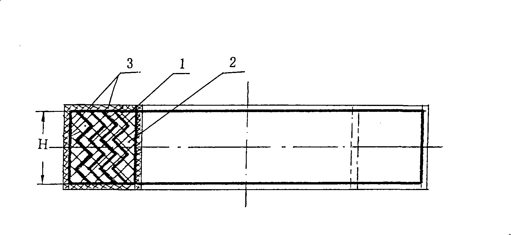
[0021] A four-sided pressure-sealed high-pressure-resistant sealing ring with a skeleton, which is formed by laminating and winding a long skeleton 1 with a width of not less than 10mm and a long flexible sealing material 2, and on both ends of the wound annular ring And the outer and inner circular surfaces are provided with cladding layer 3, its compressive strength is between 200MPa ~ 480MPa, such as figure 1 shown. During specific implementation, the skeleton 1 can be one or a combination of flat plates, corrugated plates, toothed plates or arc-shaped plates, wherein figure 1 The corrugated plate shape shown has the best compressive strength, and the skeleton 1 of the corresponding shape can be selected according to the maximum pressure surface borne by the sealing ring in the actual implementation. When the main direction of force is the end face, the skeleton can also be used Curved plate structure, the material of the frame can be a metal frame or a high-strength organic material frame. During specific manufacturing, the skeleton and the sealing filler in the middle, that is, the sealing material, should be laminated and then wound to form. The flexible sealing material 2 can be made of flexible graphite material or other materials with good formability and high compressive strength, such as pressure modified Rubber, polyester material, etc. The cladding layer 3 is preferably made of rubber or titanium fiber braids, and flexible graphite strips can also be used for cladding, and other polymer materials such as carbon fibers, high-strength glass fiber braids, etc. can also be used as cladding layer 3 materials. . During specific implementation, the height H of the strip skeleton 1 and the strip flexible sealing material 2 can be selected according to the sealing space and the required compressive strength, preferably not less than 10 mm, and its maximum width should be controlled within 50 mm and greater than 50 mm The difficulty and cost of its manufacture will be greatly increased. According to the experimental verification, the width of the framework is best between 25-50. The sealing ring made of the framework within this size range can withstand a pressure of more than 480MPa.
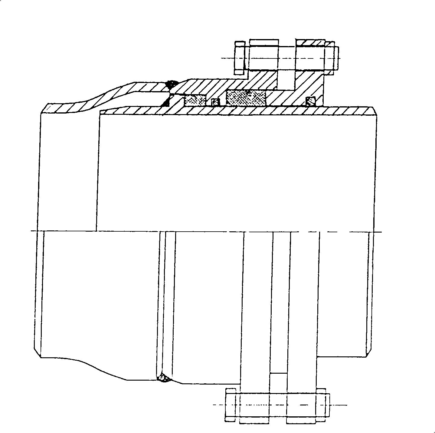
[0022] figure 2 It is a specific application example of the present invention. figure 2 The sealing ring in the rotary compensator requires four-sided sealing and high pressure resistance. After adopting the sealing ring with a thickness of 25 mm in the present invention, it is tested that when the internal pressure of the pipeline increases to 480 MPa, the inner pipe and the outer pipe make a relative rotation of 10000 After several times (standard value), there is still no leakage. After the pressure is released, the surface of the sealing ring is not damaged, but the sealing ring of the ordinary structure will leak and brittle when it is pressurized to 10MPa. After analysis, it is believed that this is due to the skeleton and package. The result of the joint action of the cladding.
[0023] The sealing ring of the present invention can be used not only in the petrochemical industry, the electric power industry, but also in similar relative motion peripheral sealing occasions with high pressure requirements.
[0024] The parts not involved in the present invention are the same as the prior art or can be realized by adopting the prior art.

PUM

PropertyMeasurementUnit
Height>= 10.0mm
Compressive strength200.0 ~ 480.0MPa
Height h10.0 ~ 50.0mm
tensileMPa
Particle sizePa
strength10

Description & Claims & Application Information

We can also present the details of the Description, Claims and Application information to help users get a comprehensive understanding of the technical details of the patent, such as background art, summary of invention, brief description of drawings, description of embodiments, and other original content. On the other hand, users can also determine the specific scope of protection of the technology through the list of claims; as well as understand the changes in the life cycle of the technology with the presentation of the patent timeline. Login to view more.

Similar technology patents

Antibody variants with enhanced complement activity

ActiveUS20110236375A1Improve bindingEnhance CDCAnimal cellsSugar derivativesFc receptorEffector functions
Owner:XENCOR

Classification and recommendation of technical efficacy words

  • Improve binding
  • Improve pressure resistance

Coriolis mass flowmeter

InactiveUS6895826B1Improve pressure resistancePrevent inertial momentDirect mass flowmetersEngineeringVibration sensor
Owner:OVAL CORP
Why Eureka
Try Eureka