A method and system for realizing common station address and coexistence of adjacent frequency

A technology of adjacent frequency and base station, which is applied in the field of coexistence of adjacent frequency co-sites, can solve problems such as high transmission power, uplink signal interference, and system spectrum efficiency reduction, and achieve good adjacent frequency co-site coexistence and reduce interference Effect

Active Publication Date: 2008-09-10
HUAWEI TECH CO LTD
View PDF1 Cites 13 Cited by
  • Summary
  • Abstract
  • Description
  • Claims
  • Application Information

AI Technical Summary

Problems solved by technology

[0015] First, the switching point time from downlink to uplink is equal to the time length of the first switching point, which is equal to 75μs. Since the time length is relatively short, the downlink signal of TD-SCDMA interferes heavily with the uplink signal of B3G/4G, or B3G /4G downlink signal interferes heavily with TD-SCDMA uplink signal, which is why the B3G/4G system and TD-SCDMA system cannot co-exist with adjacent frequency sites
[0016] Second, there are guard intervals between DL and DL, between UL and UL, and between DL and UL. These idle guard intervals will lead to a reduction in system spectral efficiency
DwPTS is located before the first switching point, and because of its high transmit power, it aggravates the interference to neighboring cells
[0017] Third, in the B3G/4G system, the communication method based

Method used


Image

  • A method and system for realizing common station address and coexistence of adjacent frequency
  • A method and system for realizing common station address and coexistence of adjacent frequency
  • A method and system for realizing common station address and coexistence of adjacent frequency

Examples


Embodiment 1

[0069] In this embodiment, by comparing the frame structure of TD-SCDMA with the frame structure represented by the time slot in the 3G next-generation evolution system, the adjacent frequency co-location of the TD-SCDMA system and the 3G next-generation evolution system is realized coexist.

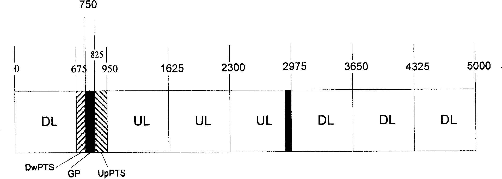
[0070] Figure 5a It is the first schematic diagram of the frame structure co-existing with TD-SCDMA adjacent frequency co-site in the embodiment of the present invention. As shown in the figure, the first row is the frame structure of TD-SCDMA, and the second row is the frame structure of the embodiment of the present invention. Figure 5a The first line shows the frame structure of TD-SCDMA with image 3 The frame structure of TD-SCDMA shown is the same. It can be seen that in each subframe, the ratio of DL to UL is 3:3 after removing the DL numbered 0.

[0071] As for the TD-SCDMA frame, the frame shown in the figure is composed of two subframes. In each subframe, include: four D...

Embodiment 2

[0080] Figure 5b It is a second schematic diagram of a frame structure co-existing with TD-SCDMA adjacent frequency co-sites according to an embodiment of the present invention.

[0081] and Figure 5a Compared with the shown frame structure, the difference is that in this embodiment the ratio of DL to UL in the first row is 4:2, and correspondingly the ratio of DL to UL in the second row is 5:2. Because in TD-SCDMA frame, TS 0 , that is, the DL provision numbered 0 cannot be counted in the DL, so the ratio of DL to UL in the first row is 4:2. In this embodiment, the method for obtaining the frame structure of the present invention from the frame structure of TD-SCDMA in the first row and Figure 5a The method is the same in the shown embodiment.

[0082] So far, the end of the Figure 5b Description of Example Two shown.

[0083] based on image 3 The frame structure of TD-SCDMA shown in the above-mentioned embodiment 1 and embodiment 2 introduces the frame structure ...

Embodiment 3

[0085] Figure 5c It is a third schematic diagram of a frame structure co-existing with TD-SCDMA adjacent frequency co-sites according to an embodiment of the present invention. see Figure 5c It can be seen that a radio frame i is 10ms, including subframe 1 and subframe 2, and both subframe 1 and subframe 2 are 5ms.

[0086] In subframe 1, each DL and UL is 665.625 μs, and DUSP and UDSP are 248.046875 μs and 9.375 μs, respectively. The length of the SCH that idles or performs synchronous operation before the DL numbered 0 is 83.203125 μs.

[0087] exist Figure 4 In , the time length of the downlink to uplink switching point is 75μs, but in this embodiment, the UDSP is extended to 248.046875μs, so the time interval of the downlink to uplink switching point is significantly extended, which can greatly reduce the impact of the downlink signal on the uplink Signal interference, so as to ensure that the TD-SCDMA system and the 3G next-generation evolution system can better co...


PUM


Abstract

The invention provides a method for realizing coexistence with an adjacent-frequency sharing station address of a time division synchronous code division multiple accesses (TD-SCDMA). The method comprises the procedures that signals are transmitted in n downlink time slots DL; before any of the downlink time slots (DL), the idling is conducted in a time span of a synchronous channel (SCH) or synchronous operation is implemented in the time span of the SCH; a time span of a first switching point is expanded into the time span of a downlink uplink shifting point (DUSP) and the idling is conducted in the time span of the DUSP; signals are transmitted in p uplink time slots UL; the idling is conducted in the time span of an uplink downlink shifting point (UDSP) and the finish time of the idleUDSP coincides with that of a second shifting point. The technical proposal of the embodiment of the invention guarantees better coexistence of the adjacent-frequency sharing station address between a 3G evolution system of the next generation and the TD-SCDMA.

Description

technical field [0001] The present invention relates to wireless communication technology, in particular to a method and system for realizing coexistence of adjacent frequency co-sites. Background technique [0002] With the rapid development of high-speed network technology and multimedia technology, the third generation mobile communication system (3G), local multipoint distributed service (LMDS), multipoint multichannel distributed system technology (MMDS) and microwave access global interoperability system (WiMAX) and other wireless networks are developing extremely rapidly, wireless networks are gradually evolving from circuit switching technology to packet switching technology, and various wireless broadband access technologies are also emerging in an endless stream. [0003] figure 1 It is a schematic structural diagram of a traditional wireless communication system in the prior art. Such as figure 1 As shown, the system includes: a base station controller, a tradi...

Claims


Application Information

Patent Timeline
IPC IPC(8): H04B7/26H04L12/28H04J13/02
Inventor 李江唐臻飞
Owner HUAWEI TECH CO LTD
Why Eureka
Try Eureka