Remote-controlled work robot

a robot and remote control technology, applied in the field of remote control actuators, can solve the problems of limiting the working range of the tool, the difficulty of processing the insertion opening of the artificial joint, and the considerable limitation of the disposition mechanism for changing the attitude of the tool, so as to achieve the effect of simplifying the spindle guide and reducing the diameter

Active Publication Date: 2012-11-27
NTN CORP
View PDF29 Cites 21 Cited by
  • Summary
  • Abstract
  • Description
  • Claims
  • Application Information

AI Technical Summary

Benefits of technology

[0017]Where one operates the remote controlled actuator while holding it by hand, wobbling, for example, of the hand holding the remote controlled actuator affects the accuracy of positioning of the tool relative to an object to be cut. For this reason, in order to accomplish the processing accurately, a substantial amount of experiences are needed. Particularly where the guide section is of a curved configuration, it is indeed difficult to predicate the position of the tool attached to the distal end of the guide section and the operation is further complicated and difficult to accomplish. This also results in an increase of the length of time required to finish the cutting. Where the remote controlled actuator is used in the artificial joint replacement surgery, the increased length of time required to accomplish the cutting tends to impose a substantial amount of load on the patient.
[0038]During the processing, the tool and the to-be-processed object evolve heat. However, the use of the tool cooling device is effective to allow the tool and the to-be-processed object to be cooled with the cooling liquid.

Problems solved by technology

Whatever the pipe take any shape, however, the working range of the tool is limited by the shape of the pipe and, therefore, difficulties have been encountered in processing the artificial joint insertion opening so that the living bone and the artificial joint may have smooth contact surfaces and, yet, skin incision and muscular scission are minimized at the same time.
Accordingly, the processing of the artificial joint insertion opening is more difficult to achieve than generally considered.
It has, however, been found that since the tool is connected to the distal end of the elongated pipe, disposition of a mechanism for changing the attitude of the tool is considerably limited and, therefore, artifices are required to overcome those limitations.
), but nothing has yet been suggested which has a capability of changing the attitude of the tool by remote control.
Where one operates the remote controlled actuator while holding it by hand, wobbling, for example, of the hand holding the remote controlled actuator affects the accuracy of positioning of the tool relative to an object to be cut.
Particularly where the guide section is of a curved configuration, it is indeed difficult to predicate the position of the tool attached to the distal end of the guide section and the operation is further complicated and difficult to accomplish.
This also results in an increase of the length of time required to finish the cutting.
Where the remote controlled actuator is used in the artificial joint replacement surgery, the increased length of time required to accomplish the cutting tends to impose a substantial amount of load on the patient.

Method used


Image

  • Remote-controlled work robot
  • Remote-controlled work robot
  • Remote-controlled work robot

Examples


first embodiment

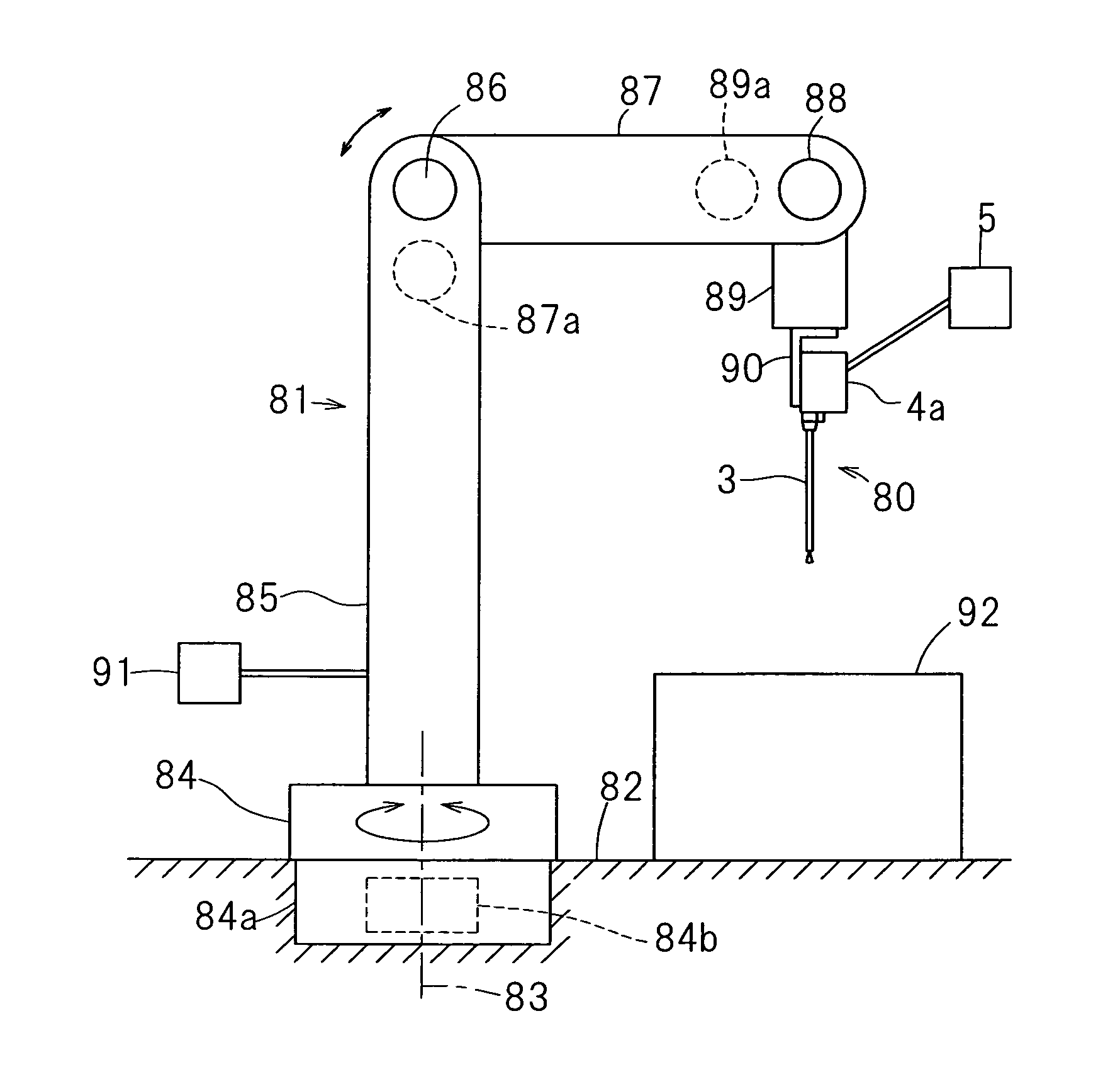
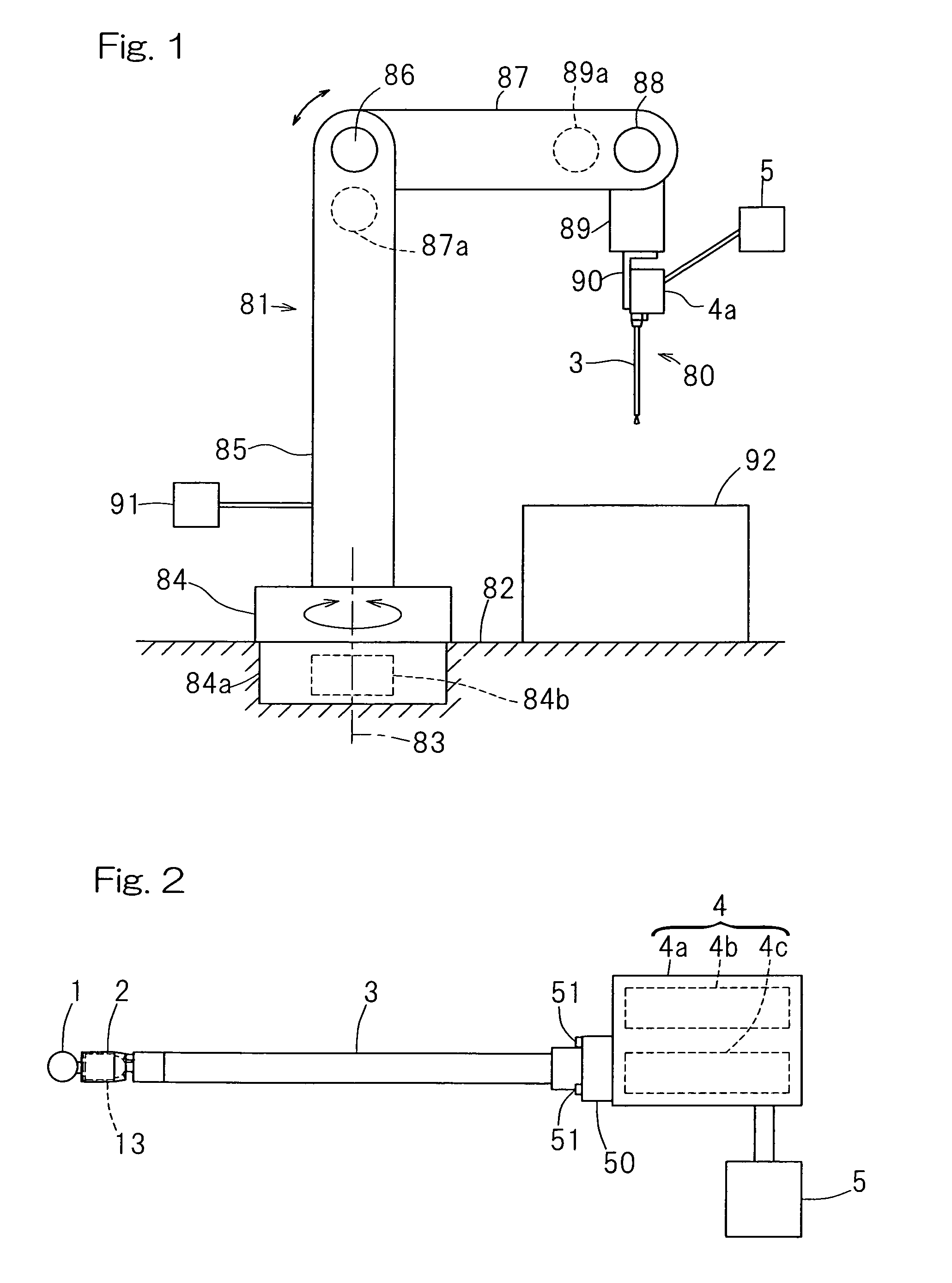
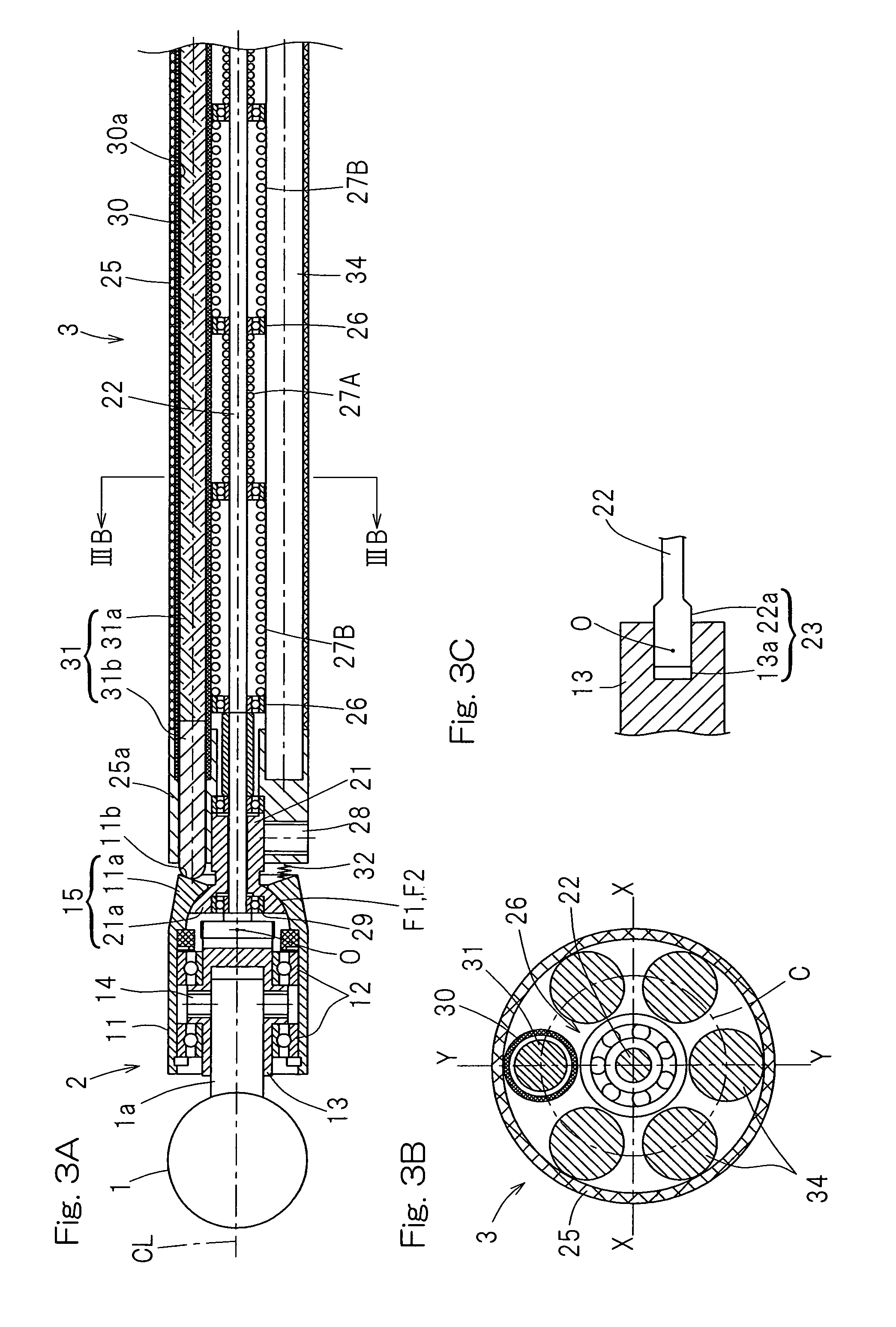
[0107]Even the remote controlled actuator 80 having the curved spindle guide section 3 is of a structure basically similar to that shown in and described with reference to FIGS. 3A to 4B in connection with the previously described first embodiment of the present invention in which the spindle guide section 3 has been shown and described as straight in shape, except for the difference in shape of the spindle guide section 3. It is, however, to be noted that where the spindle guide section 3 is of a curved shape, the outer shell pipe 25, the guide pipe 30 and the reinforcement shafts 34 have to be also curved. Also, the rotary shaft 22 is preferably made of a material easy to deform and, for example, a shape memory alloy is a suitable material for the rotary shaft 22.

[0108]FIG. 7 illustrates a third preferred embodiment of the present invention, in which the support device 81 is of a structure different from that has been described above. The support device 81 for the remote controlle...

fourth embodiment

[0109]A fourth preferred embodiment of the present invention, in which the support device 81 of a further different structure is employed, is shown in FIG. 8, reference to which will now be made. The support device 81 for the remote controlled work robot according to the present invention is made up of a three-degrees-of-freedom system 81a of a structure similar to the support device 81, shown in and described with reference to FIGS. 1 and 5, and a small sized multi-degrees-of-freedom system 81b provided in the pivot arm 89 of the three-degrees-of-freedom system 81a, and the remote controlled actuator 80 is mounted supported by the small sized multi-degrees-of-freedom system 81b through the mounting stand 90. The small sized multi-degrees-of-freedom system 81b may be any type provided that it has a plurality of degrees of freedom and is not therefore specifically limited to that shown and described. However, for the small sized multi-degrees-of-freedom system 81b, a mechanism of a h...

fifth embodiment

[0111]FIG. 9 illustrates a fifth preferred embodiment of the present invention utilizing the support device 81 of a yet different structure. The support device 81 used in the remote controlled work robot is itself of the small size multi-degrees-of-freedom system of the structure similar to the small size multi-degrees-of-freedom structure shown in and described with particular reference to FIG. 8 and, hence, the support device 81 secured to the ceiling 94, defining the base, and the remote controlled actuator 80 is supported by this support device 81 through the mounting stand 90. The support device 81, which is the small sized multi-degrees-of-freedom system, is controlled by the support device controller 98 for the small sized multi-degrees-of-freedom system. It is, however, to be noted that the support device 81 may be secured to the ceiling 94 through a suitable mounting member (not shown) instead of being secured directly to the ceiling 94. In such case, the mounting member d...


PUM

PropertyMeasurementUnit
bending angleaaaaaaaaaa
angle of swivelaaaaaaaaaa
arm angleaaaaaaaaaa

Abstract

A remote controlled work robot including a remote controlled actuator and a support device therefor. The remote controlled actuator includes a spindle guide section of an elongated configuration, a distal end member fitted to a distal end of the spindle guide section through a distal end member coupling structure for alteration in attitude, and a drive unit housing connected with a base end of the spindle guide section. The distal end member rotatably supports a spindle for holding a tool. The support device includes a single degree-of-freedom system, in which the remote controlled actuator has a degree of freedom in one direction, or a multi-degrees-of-freedom system, in which the remote controlled actuator has a two or more degrees of freedom relative to a base on which the support device is installed. A drive source and is also provided for driving the degree-of-freedom system.

Description

CROSS REFERENCE TO THE RELATED APPLICATION[0001]This application is a continuation application, under 35 U.S. §111(a) of international application No. PCT / JP2010 / 057545, filed Apr. 28, 2010, which claims priority to a Japanese patent application No. 2009-113269, filed May 8, 2009, the entire disclosure of which is herein incorporated by reference as a part of this application.BACKGROUND OF THE INVENTION[0002]1. (Field of the Invention)[0003]The present invention relates to a remote controlled actuator capable of altering the attitude of a tool by remote control and a support device therefor and, more particularly, to a remote controlled work robot for use in the application such as, for example, medical or mechanical processing.[0004]2. Description of Related Art[0005]Remote controlled actuators are currently known; some are used in the medical field for osteal treatment and some are used in the mechanical processing field for drilling and cutting. Any of those remote controlled act...

Claims


Application Information

Patent Timeline
Patent Type & Authority Patents(United States)
IPC IPC(8): B25J17/02
CPCA61B17/1631A61B19/2203B23B39/14B25J15/0019B25J17/0266B25J9/0048A61B17/1624A61B17/1626A61B2017/1651A61B2017/1653A61B2019/2226A61B34/30A61B2034/304B25J17/02A61B17/16B25J19/00
Inventor ISOBE, HIROSHIOZAKI, TAKAYOSHI
Owner NTN CORP
Why Eureka
Try Eureka