Motor vehicle braking system

A brake system and motor vehicle technology, applied in the direction of brakes, vehicle components, brake transmissions, etc., can solve the problems of not being used, etc., to improve operational reliability, save installation space and seals, and avoid technical complexity Effect

Inactive Publication Date: 2008-09-10
CONTINENTAL TEVES AG & CO OHG
View PDF1 Cites 49 Cited by
  • Summary
  • Abstract
  • Description
  • Claims
  • Application Information

AI Technical Summary

Problems solved by technology

In the brake systems known from the prior art, it is considered disadvantageous that in the "brake-by-wire" mode of operation the pressure regulating valve is disabled by closing said chamber, so that the "brake-by-wire" The brake pressure can only be introduced by a solenoid-actuatable valve arrangement, wherein the potential of the pressure regulating valve for controlling the necessary pressurized fluid volume flow is not used
Furthermore, in the brake systems known from the prior art, the flow of pressurized fluid from the pressure supply into the wheel brake circuit during operation of the brake system is considered to be disadvantageous
For the wheel brake circuit, the demands on the pressurized fluid are much higher with regard to possible contamination by air bubbles, so only absolutely gas-tight hydraulic accumulators can be used in the brake systems known from the prior art

Method used


Image

  • Motor vehicle braking system
  • Motor vehicle braking system
  • Motor vehicle braking system

Examples


Embodiment Construction

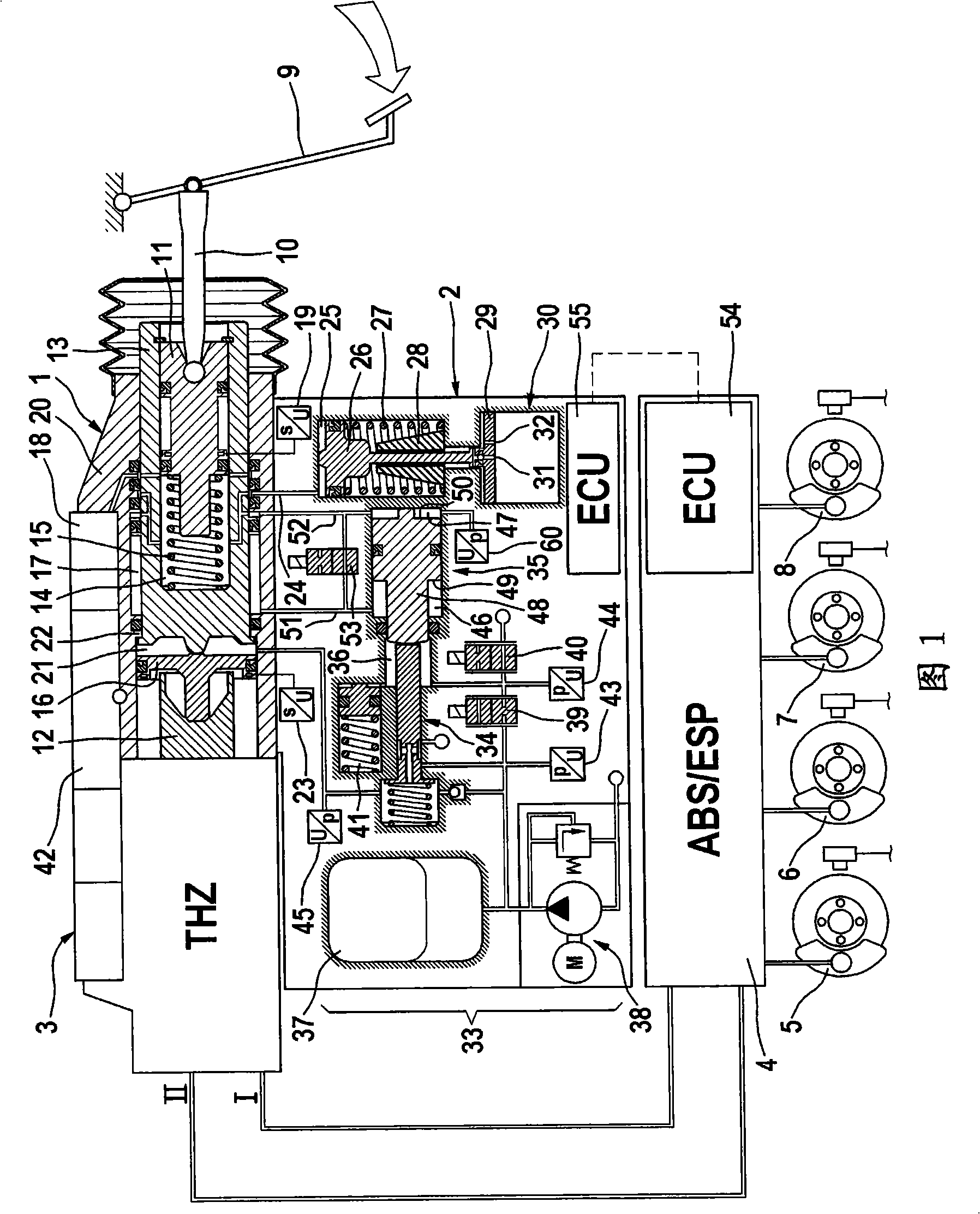
[0029] The brake system according to the invention shown in the figure essentially comprises an actuating device 1, a hydraulic control unit 2 and a brake master cylinder or tandem (brake) master cylinder 3, wherein the actuating device and the control unit Forms a brake booster, the brake master cylinder or tandem (brake) master cylinder is operatively arranged downstream of the brake booster and is connected in its pressure chamber, not shown, to the wheel brake circuits I, II , these wheel brake circuits supply the wheel brakes 5-8 of the motor vehicle with hydraulically pressurized fluid in connection with known ABS / ESP hydraulic assemblies or controllable wheel brake pressure modulation modules 4 . The wheel brake pressure modulation module 4 is associated with an electronic control and regulation unit 54 . The actuating device 1 housed in a housing 20 connected to the tandem master cylinder 3 can be driven by means of a brake pedal 9 which acts on the first piston 11 of ...


PUM


Abstract

The invention relates to a 'Brake-by-wire' braking system comprising a main cylinder (3) and wheel braking circuits (I, II) associated thereto and two brake booster pressure fluid circuits which are completely separated from said wheel braking circuits wheel braking circuits. In order to use a pressure control valve (34) associated with the first brake booster pressure fluid circuit for controlling a pressure in an intermediate space (21) not only by pressing on a pedal but also electrically, means (39, 40) for electrically controlling the intermediate space (21) pressure are provided with the pressure control valve (34).

Description

technical field [0001] The invention relates to a braking system for a motor vehicle comprising: [0002] The master cylinder connected with the wheel brake circuit; [0003] a first piston coupled to the brake pedal via a pressure rod that transmits the actuation force; [0004] A second piston that can actuate the master cylinder; [0005] a third piston actuatable by the first piston and force-transmittingly connectable to the second piston; [0006] at least one elastic element forming a pedal displacement simulator for a comfortable pedal feel for the driver of the vehicle; [0007] a hydraulically loadable gap between the second piston and the third piston, wherein pressure loading of the gap causes the second piston and the third piston to be loaded in opposite directions; [0008] a hydraulic chamber delimited by the third piston, closable by a shut-off valve, by which the movement of the third piston in the actuating direction is blocked if required; [0009] · a...

Claims


Application Information

Patent Timeline
Patent Type & Authority Applications(China)
IPC IPC(8): B60T8/44B60T8/40B60T13/14
Inventor L·席尔S·德鲁姆P·里特
Owner CONTINENTAL TEVES AG & CO OHG
Why Eureka
Try Eureka