
No-frost refrigeration device

A technology of refrigeration appliances and evaporators, which is applied in the direction of refrigerators, refrigeration components, refrigeration and liquefaction, etc. It can solve the problems of difficult locking of the rear wall of air pipes and achieve the effect of small size

Inactive Publication Date: 2008-09-10
BSH BOSCH & SIEMENS HAUSGERAETE GMBH
View PDF0 Cites 17 Cited by
  • Summary
  • Abstract
  • Description
  • Claims
  • Application Information

AI Technical Summary

Problems solved by technology

The rubber lip, which yields in a flexible manner under pressure, makes the locking of the rear wall of the air duct difficult

Method used


Image

  • No-frost refrigeration device
  • No-frost refrigeration device
  • No-frost refrigeration device

Examples


Embodiment Construction

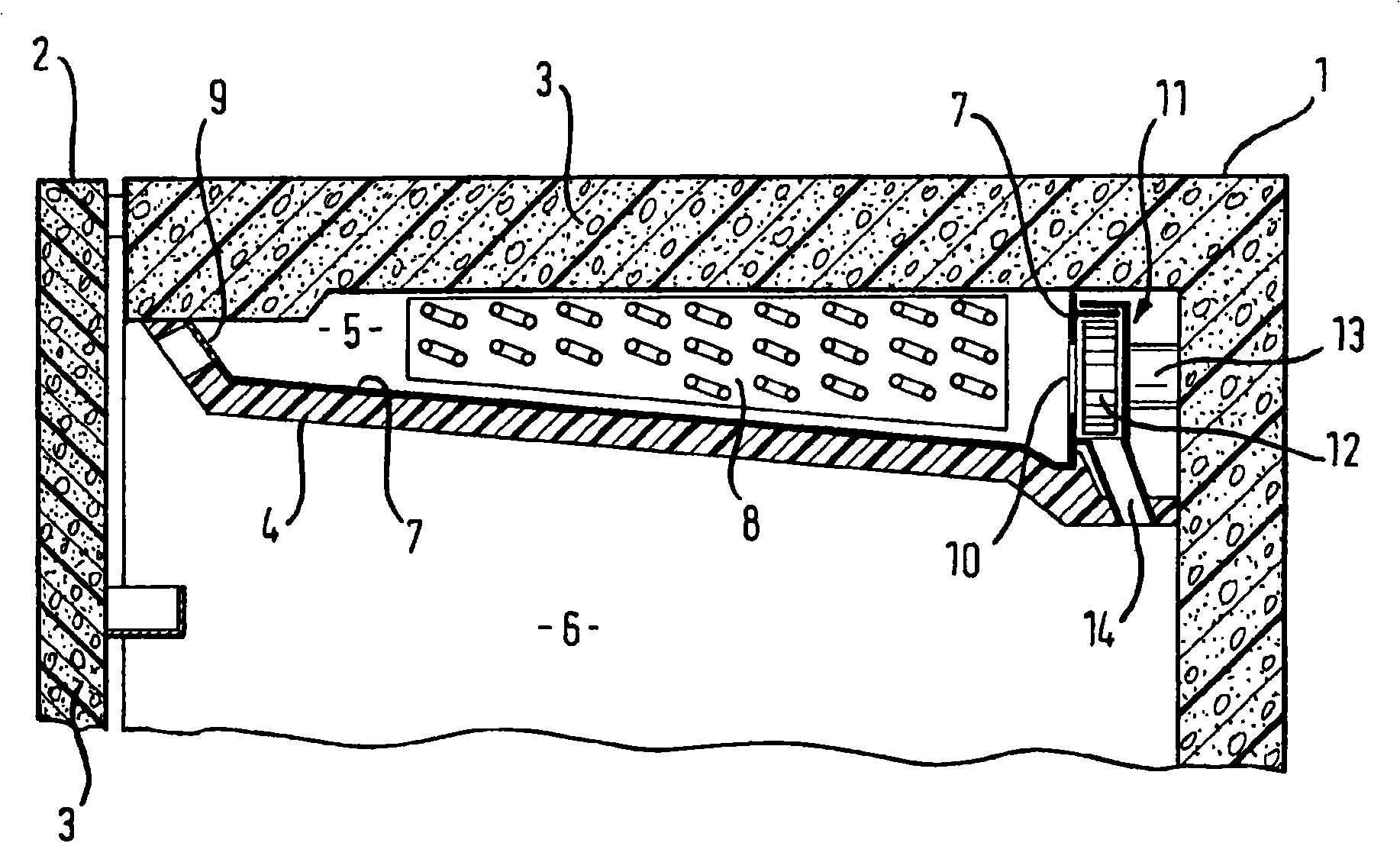
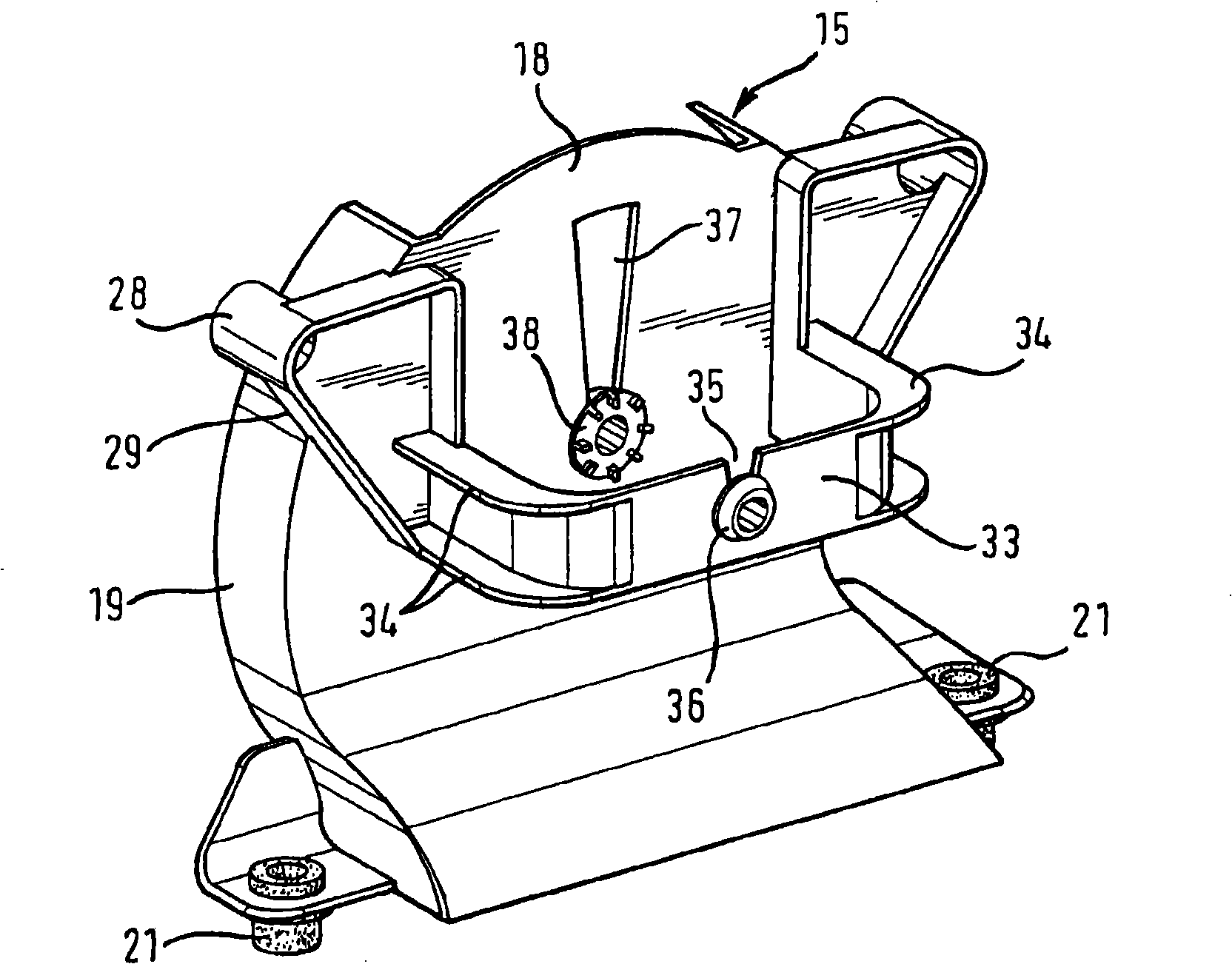
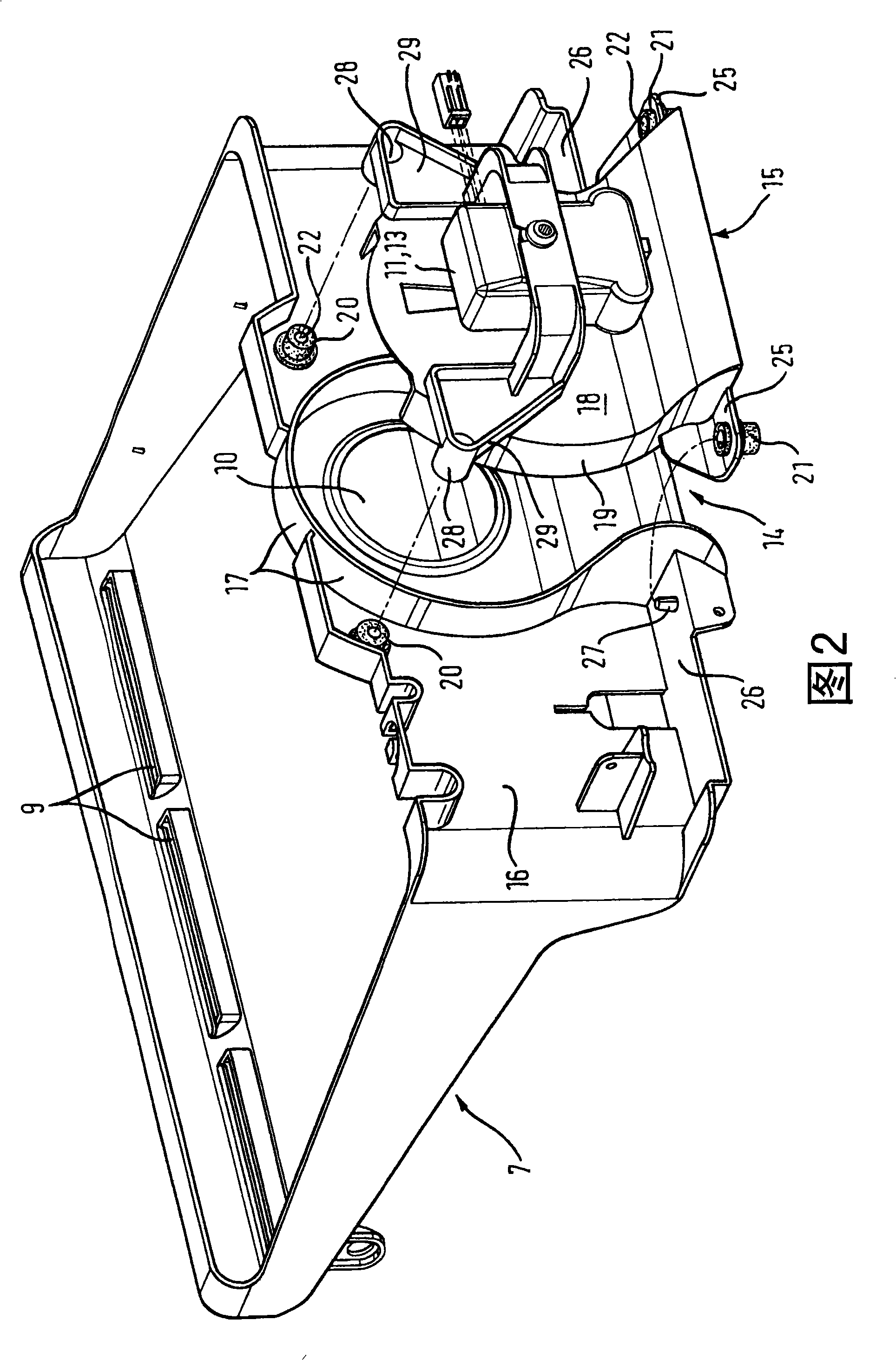
[0021] figure 1 A schematic section through the upper region of the refrigeration appliance according to the invention is shown. The refrigeration appliance has a frame 1 and a door 2 , each realized in a conventional manner, with a hollow body filled with a layer 3 of insulating foam. The interior of the frame 1 is divided by similar insulating partition walls 4 into an evaporator chamber 5 and a cooling compartment 6 . The partition wall 4 is formed by the underside of a hood support 7 for the evaporator unit, on which a layer evaporator 8 known per se is mounted. A support 7 is mounted at a distance from the top of the frame 1 and, together with the side walls of the frame, defines an evaporator chamber 5 . The support 7 also has an air inlet channel 9 on its side facing the door 2 and an air outlet channel 10 on its side facing the rear wall of the frame 1 . In the rear area of ​​the evaporator chamber 5, behind the air outlet channel 10 of the support 7, a fan 11 with ...


PUM


Abstract

The invention relates to an evaporator unit for a no-frost cooling device which comprises an evaporator, a support (7) which surrounds the evaporator, wherein a passage (10) which leads to an air channel (14) is formed in a wall (16) of the support (7), and a ventilator (11) which is mounted on the passage (10) such that vibrations are dampened and is supported by a wall element (15) of the air channel (14) which is opposite the passage (10). The wall element (15) is secured to the support (7) by means of vibration-dampening elements (20, 21).

Description

technical field [0001] The invention relates to a frost-free refrigeration appliance having an evaporator unit. Such evaporator units traditionally consist of an evaporator; a shroud support defining an evaporator cavity defined by the frame of the refrigerating appliance, in which the inlet and outlet passages to the evaporator cavity are embedded, and the evaporator and a ventilator connected to the support for exhausting air from the support into an air duct through which the air reaches the cooling chamber of the refrigeration appliance. With the known evaporator unit, the ventilator is mounted directly on the part of the supporting wall that has the outlet opening embedded in it, and this part is connected to the rest of the wall by a surrounding flexible rubber lip and is thus able to vibrate in a damped manner . The rear wall of the air duct connected to the air outlet opening is locked in the slot of the rubber lip. Background technique [0002] The result of moun...

Claims


Application Information

Patent Timeline
Patent Type & Authority Applications(China)
IPC IPC(8): F25D17/06F04D29/66H02K5/24
CPCF25B2500/13F25D23/006F25D2317/0665F04D29/668H02K5/24F25D2317/0681F25D2317/0683F25D2317/0655F25D17/067
Inventor M・马利希
Owner BSH BOSCH & SIEMENS HAUSGERAETE GMBH
Learn More