Switch reluctance machine rotor angular position and rotation speed detection device and method

A switched reluctance motor and speed detection technology, which is applied in the field of angular position and speed devices, can solve the problems that the sensor signal is not suitable for long-distance transmission distance, easily affected by dust and rain, and the sensor protection level is low, so as to achieve improvement Low-speed response, improved high-speed accuracy, and small error effects

Inactive Publication Date: 2008-09-17
BEIJING CHINA TEX MECHANICAL & ELECTRICAL ENG
View PDF0 Cites 25 Cited by
  • Summary
  • Abstract
  • Description
  • Claims
  • Application Information

AI Technical Summary

Problems solved by technology

The protection level of the sensor is relatively low, and it is easily affected by dust and rain. The

Method used


Image

  • Switch reluctance machine rotor angular position and rotation speed detection device and method
  • Switch reluctance machine rotor angular position and rotation speed detection device and method
  • Switch reluctance machine rotor angular position and rotation speed detection device and method

Examples


Embodiment Construction

[0036] The present invention will be described in detail below in conjunction with the accompanying drawings and specific embodiments.

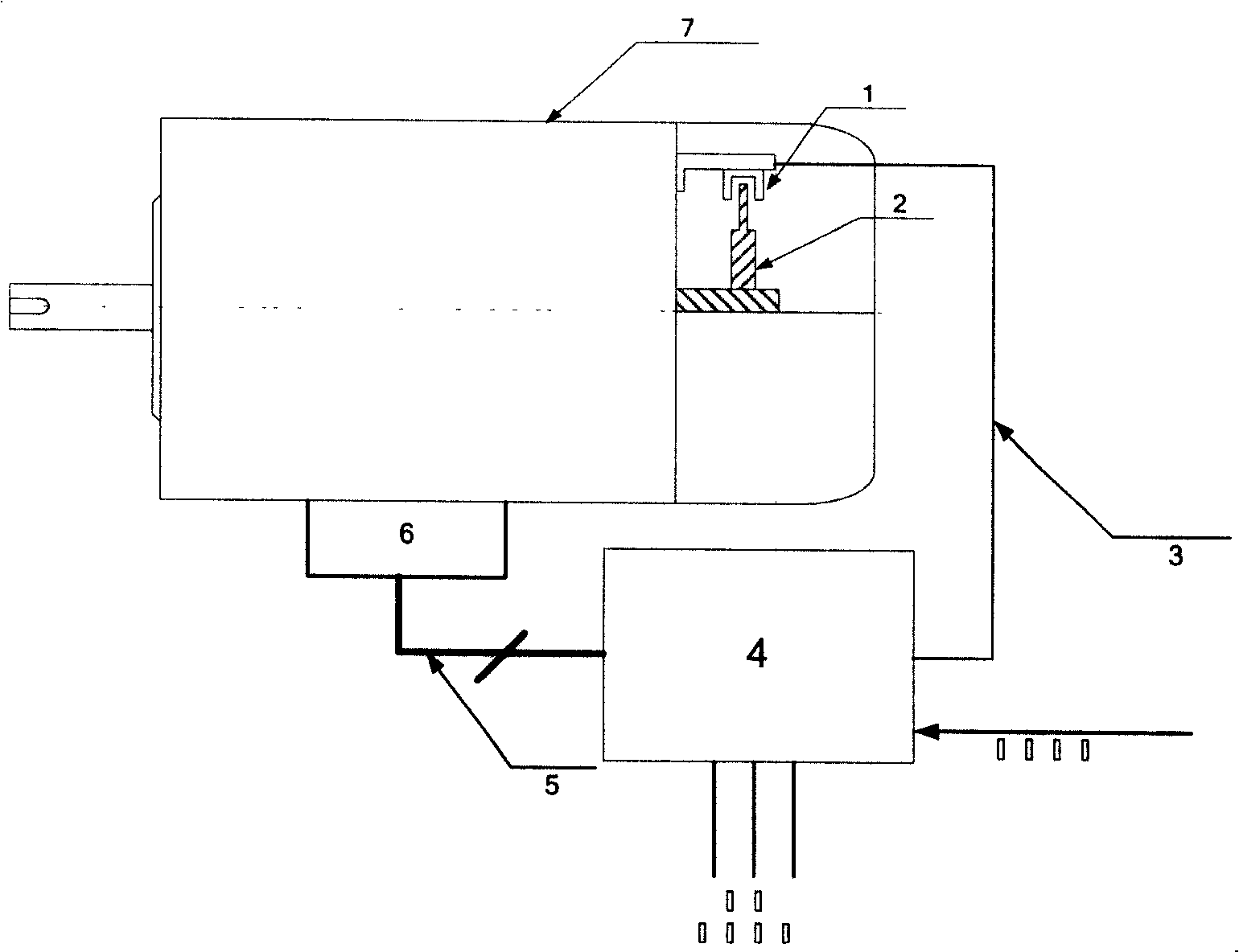
[0037] The angular position and rotational speed detection device of the switched reluctance motor rotor of the present invention, the rotary encoder 11 and the signal processing circuit 12 are placed in the sealing cover 15 of the motor 7 and fixed on the support plate 8 . The rotary encoder 11 is a 10-bit absolute rotary encoder, the shaft type is connected to the motor shaft 13 through the elastic connector 14, the collector is open circuit output, gray code, negative logic output, and the rotary encoder 11 is powered by 15V powered by.

[0038]The absolute rotary encoder 11 is connected to a signal processing circuit 12, and the signal processing circuit 12 is connected to external components, such as the controller 4 and the like. The signal processing circuit 12 includes an encoder signal preprocessing unit, a microprocessor unit, and ...


PUM


Abstract

The invention relates to a device for detecting the angular position and the speed of the switch magnetic resistance motor and method, comprising a rotary encoder and a signal processing circuit mounted in the motor and fixed on a support plate, wherein the rotary encoder is connected with the main axis of the motor. The rotary encoder collects and transfers the angular position signals of the rotator to the encoder signal pretreating unit of the signal processing circuit. The encoder signal pretreating unit converts the output signal of the encoder into the signal capable for being received by the microprocessor unit. The microprocessor unit processes the angular position signals and calculates the speed of the motor. The communication unit sends the angular position signals and speed signals by serial communication bus. The connection line of the said device with the outside is simple and the antijamming capability is strong. The device device for detecting the angular position and the speed of the switch magnetic resistance motor is suitable for long distance transmission with high resolution, easy operation, small error and no zero setting by manpower.

Description

technical field [0001] The invention relates to a device and method for detecting the angular position and rotating speed (including size and direction) of a switched reluctance motor rotor, in particular to an angular position of a switched reluctance motor rotor based on an absolute rotary encoder and serial bus communication. Position and rotational speed detection device and method. Background technique [0002] The switched reluctance speed control motor is generally composed of two parts: the controller and the motor. The former is equipped with power circuits, control circuits and other components, and the latter includes stators, rotors, angular position sensors, etc. [0003] The switched reluctance motor has a stator and rotor double-salient pole structure. The stator and rotor are made of laminated silicon steel sheets. The stator poles are equipped with concentrated windings, and the rotor has no windings. Switched reluctance motors can be designed with differen...

Claims


Application Information

Patent Timeline
IPC IPC(8): G01R31/34G01B7/00G01D5/00G01P3/42
Inventor 毕伟苏建中李宪平
Owner BEIJING CHINA TEX MECHANICAL & ELECTRICAL ENG
Why Eureka
Try Eureka