

Multiplexed optical signal transmission apparatus
A signal transmission device and signal technology, which are applied in multiplex communication, wavelength division multiplexing system, time division multiplexing system, etc., can solve the problems of wrong operation by maintainers, increased workload of maintainers, and server impact.
- Summary
- Abstract
- Description
- Claims
- Application Information
AI Technical Summary
Problems solved by technology
Method used
Image

Examples
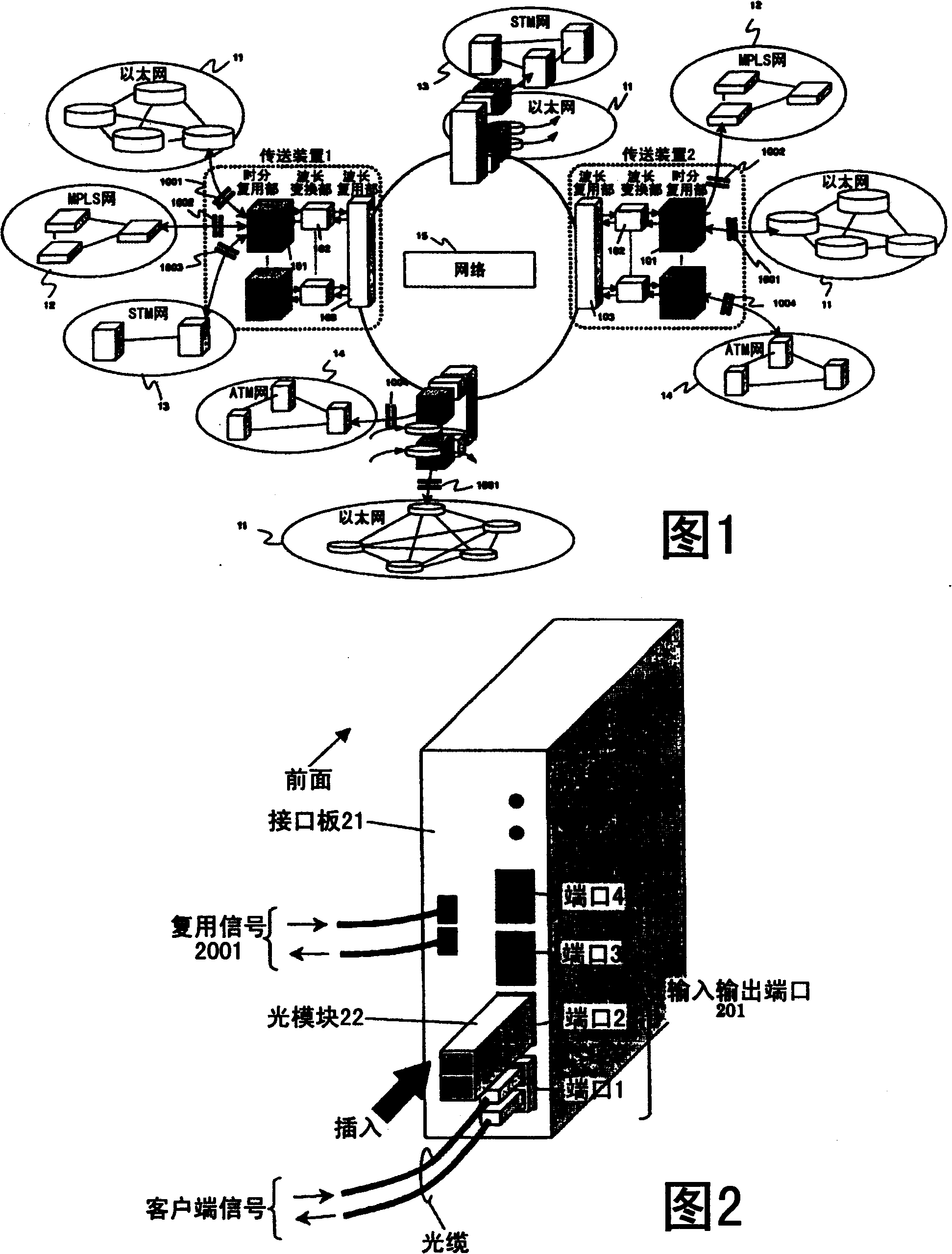
no. 1 example
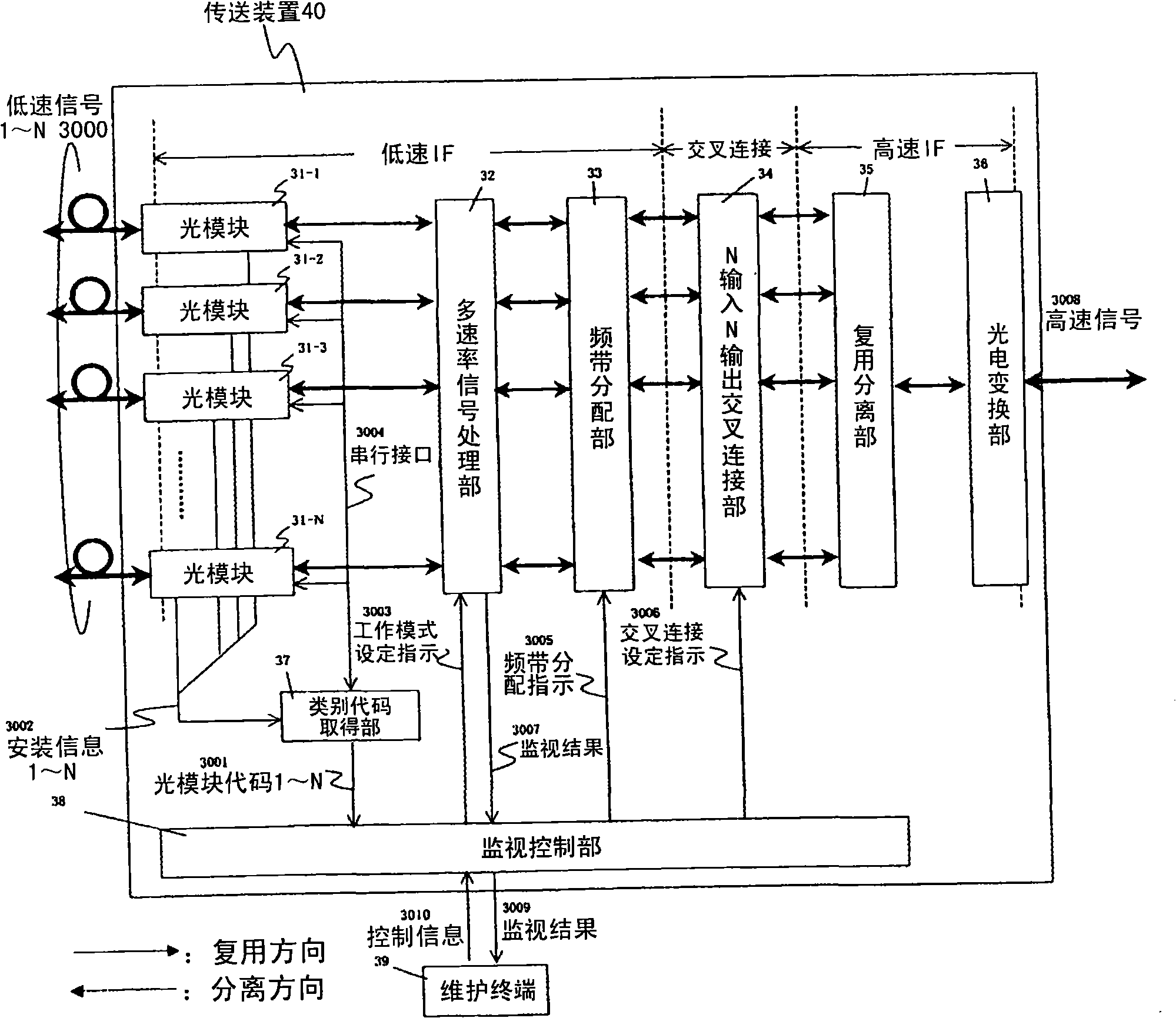
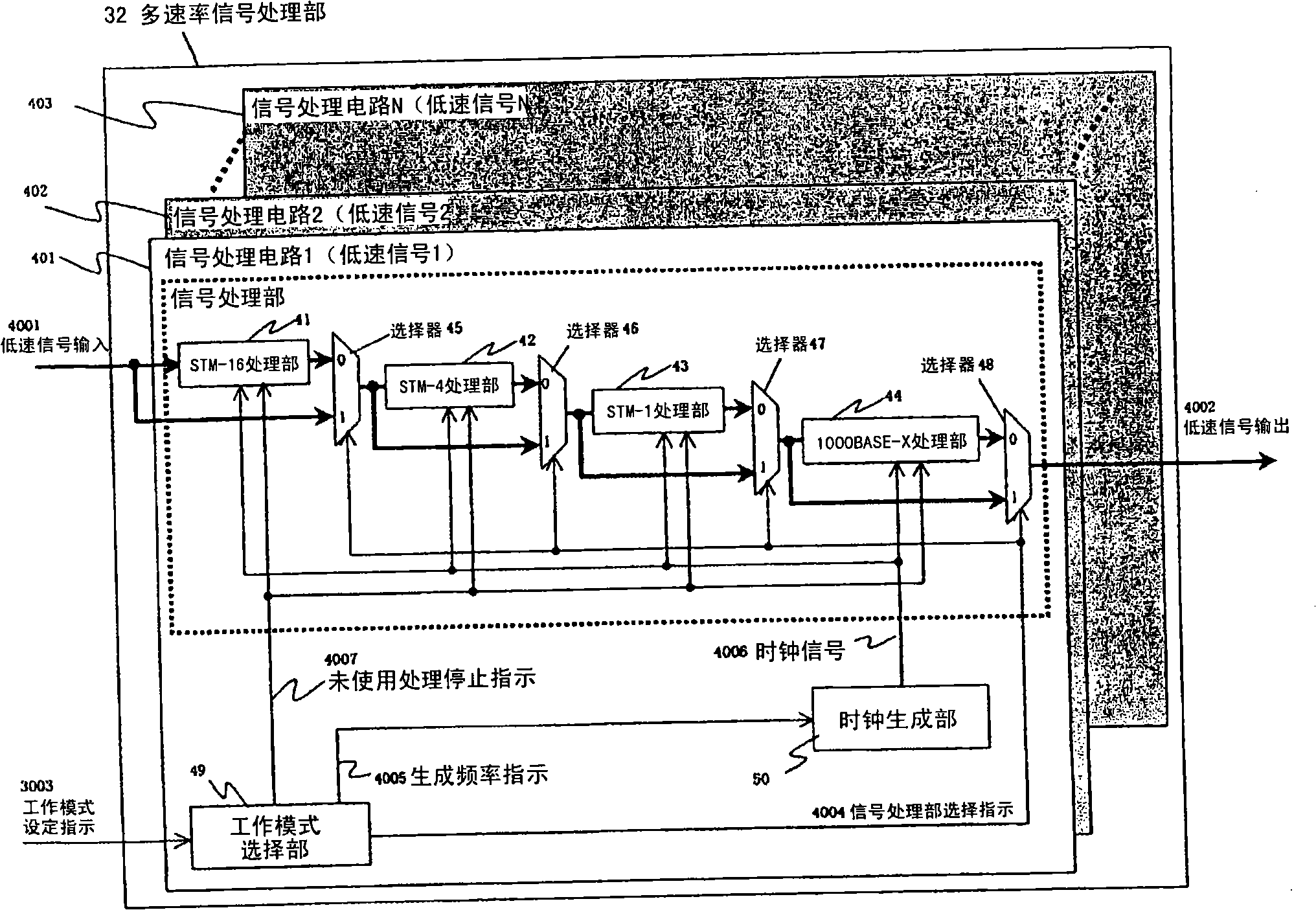
[0039] image 3 The configuration of the conveying device 40 according to the first embodiment of the present invention is shown. The transmission device of the first embodiment includes: optical modules 31-1 to 31-N, which receive N low-speed signals 1 to N3000 with mutually different optical types or signal speeds or frame formats as optical signals from the WAN line, respectively After being converted into N electrical signals, it is sent to the multi-rate signal processing unit 32; and on the contrary, it receives N electrical signals from the multi-rate signal processing unit 32, converts them into N optical signals, and sends multi-low-speed signals 1 to N3000 to WAN line transmission; the multi-rate signal processing unit 32, for N signals with different signal speeds and frame formats, according to the operation mode setting instruction 3003 from the monitoring control unit 38, can independently respond in the multiplexing direction and the separating direction Properl...
no. 2 example
[0067] In the first embodiment, one category code uniquely determines the operation mode selection indication, optical module category information, signal category information and frequency band allocation setting instructions, and one category code corresponds to two or more signal categories In the case of optical modules, they cannot be uniquely identified with only the category code. An example of this case will be described as a second example of the present invention.
[0068] In this embodiment, it is the case that an XFP type optical module is applied, and the frame format and signal speed that can accommodate the signal are completely different, and the STM-64 (signal speed: 9953.28Mbit) stipulated by ITU-T G.707 is used. / s), 10GBASE-R (signal speed: 10312.5Mbit / s) and 10GBASE-W (signal speed: 9953.28Mbit / s) regulated by IEEE802.3 as an example of the transmission device of the multi-rate signal processing unit Be explained.
[0069] Figure 15 The configuration o...
PUM
 Abstract
Description
Claims
Application Information