
Debugging method and debugging system

A debugging method and technology of debugging points, which are used in transmission systems, digital transmission systems, electronic circuit testing, etc.

Inactive Publication Date: 2010-07-21
SUNPLUS TECH CO LTD +1
View PDF3 Cites 0 Cited by
  • Summary
  • Abstract
  • Description
  • Claims
  • Application Information

AI Technical Summary

Problems solved by technology

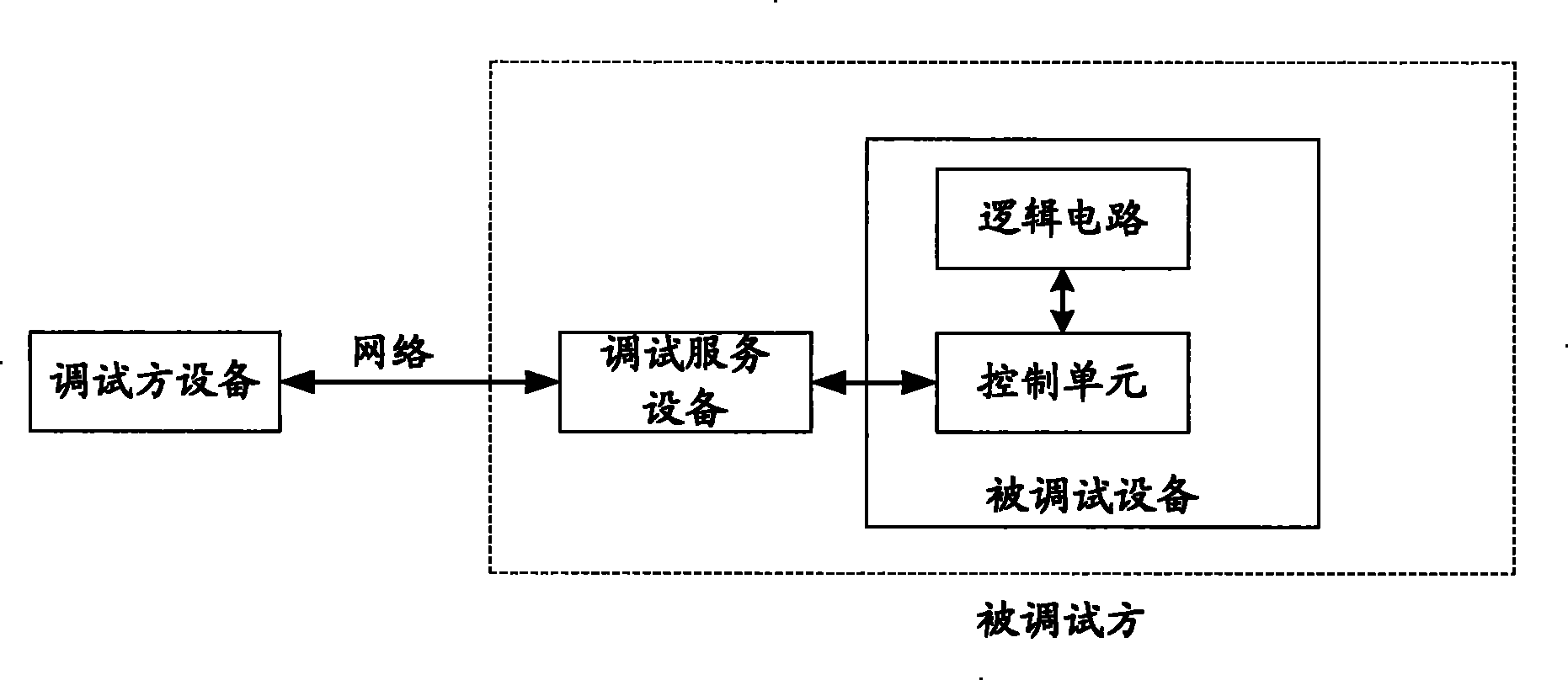
[0004]However, in the existing remote debugging scheme, the debugger can only locate the fault according to the program code obtained from the control unit, and the debugged equipment includes not only the control unit , also includes logic circuits
The output data after the control unit runs the program code may be processed by the logic circuit. If there is no problem with the program code, but the logic circuit fails, it will also cause the debugged device to malfunction.
It can be seen that because the existing remote debugging scheme can only obtain the program code and cannot obtain the status information of the logic circuit, it is impossible to determine the fault of the logic circuit
[0005] At present, the commonly used local debugging system also relies on the debugging service equipment provided by the supplier to obtain the program code of the debugged equipment as the basis for fault judgment, which also has the disadvantage of being inconvenient to obtain Defects in logic circuit state information

Method used


Image

  • Debugging method and debugging system
  • Debugging method and debugging system
  • Debugging method and debugging system

Examples


Embodiment 1

[0058] image 3 It is a structural diagram of the remote debugging system in Embodiment 1 of the present invention. like image 3 As shown, the system includes a client 210 , a server 220 and a debugged device 230 . The communication between the client 210 and the server 220 is based on the TCP / IP protocol. in,

[0059] image 3 The client 210 in specifically includes a debugging instruction generation unit 211 and a communication unit 212:

[0060] The debugging command generating unit 211 is configured to generate a debugging command and send it to the communication unit 212 ; in this embodiment, the debugging command is a reading command for reading the level of an I / O pin in the logic circuit 231 .

[0061] The communication unit 212 is configured to establish a communication channel with the server, send the debugging instruction to the server 220 through the established communication channel, and receive the execution result of the debugging instruction from the ser...

Embodiment 2

[0076]In this embodiment, the client can also obtain the program code from the debugged device through the server, so as to determine the fault in the program code, and send the correct program code back to the debugged device after debugging. When the client sends a new program code to the device to be debugged, the client needs to enter the In-System Programming (ISP, In-System Programming) mode, write the new program code and restart. Entering ISP mode and restarting are controlled by ISP switch pin and system reset (RESET) pin on the debugged device respectively. The remote debugging system in the embodiment of the present invention can further remotely control the levels of the ISP switch pin and the RESET pin. If the micro control unit (MCU) of the device to be debugged, that is, the control unit that executes the program code, has a reset circuit and an ISP control circuit, the ISP switch pin and the RESET pin are on the MCU of the device to be debugged; If the logic c...

Embodiment 3

[0097] In this embodiment, the remote debugging system integrates the remote debugging function provided by the existing GDB debugging tool, so that the user can single-step execute the program code on the device being debugged, set breakpoints, view content, etc. from the client through remote debugging. operate. In the prior art, GDB is an abbreviation of GNU symbolic debugger, which is a type of debugging tool provided by GNU. GDB provides a local debugging machine and a debugging agent, which are physically separated. The debugging agent is set on the device to be debugged and connected to the control unit of the device to be debugged. The local debugging machine is set on the debugging side. The debugging agents communicate according to the GDB Remote Serial Protocol (RSP, Remote Serial Protocol). The RSP protocol defines the format of the data packet in the communication between the local debugging machine and the debugging agent. RSP is a simple, ASCII-based protocol ...


PUM


Abstract

The invention discloses a debugging method, comprising: a debugging service equipment receives and reads a reading order of debugging point level in logic circuit of a debugged equipment, and reads the debugging point level according to the reading order via a physical transmission channel between the debugging service equipment and the debugging point. The invention also discloses a debugging system. The debugging service equipment in the debugging system is connected with the debugging point of the logic circuit in the debugged equipment via the physical transmission channel. After receiving the reading order, the debugging service equipment reads the debugged point level pointed out by the reading order via the physical transmission channel. Using the invention can gain a state of the logic circuit, so as to determine logic circuit fault.

Description

Technical field [0001] The present invention involves debugging technology, and specifically involves debugging methods and debugging systems. Background technique [0002] In order to reduce the cost generated by the maintenance of the faulty equipment at the equipment site, the remote debugging system has currently appeared, so that engineers can debug and maintain the faulty equipment in different places.For example, the selling board that has been sold failed during the user's use process, the supplier engineer can remotely debug the development board through the remote debugging system to help users solve the failure. [0003] figure 1 For the structural diagram of the remote debugging system in the existing technology, such as figure 1 It shows that the system includes the derivative equipment, debugging service equipment and commissioning equipment. Among them, the debugging service equipment and the commissioning device are the tested party.When the debugging device fail...

Claims


Application Information

Patent Timeline
Patent Type & Authority Patents(China)
IPC IPC(8): H04L12/24G01R31/28
Inventor 王泰运杨兴华
Owner SUNPLUS TECH CO LTD
Learn More