
Method and device for identifying congestion status of data transmission channel

A congestion state and transmission channel technology, applied in digital transmission systems, transmission systems, data exchange networks, etc., can solve problems such as hardware or software complexity, high hardware requirements, and processing capacity limitations, and achieve data priority scheduling , Simplify the processing flow, and ensure the effect of service quality

Inactive Publication Date: 2008-09-17
DATANG MOBILE COMM EQUIP CO LTD
View PDF0 Cites 23 Cited by
  • Summary
  • Abstract
  • Description
  • Claims
  • Application Information

AI Technical Summary

Problems solved by technology

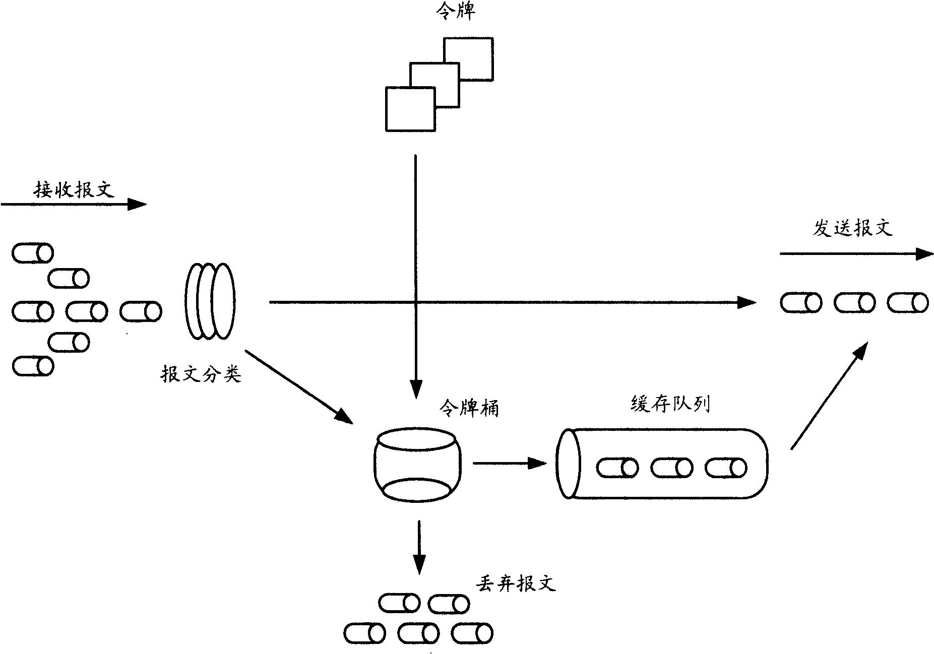
[0025] (2) Data flow arrival rate < token inflow rate
[0032] 3. CAR: Data packets can continue to be sent, but special marking is required, such as setting a lower priority
The disadvantage of this mechanism is that the current synchronization of ATM layer management and AAL2 virtual channel congestion information is very complicated both in hardware and software. processing power limitations

Method used


Image

  • Method and device for identifying congestion status of data transmission channel
  • Method and device for identifying congestion status of data transmission channel
  • Method and device for identifying congestion status of data transmission channel

Examples


Embodiment 1

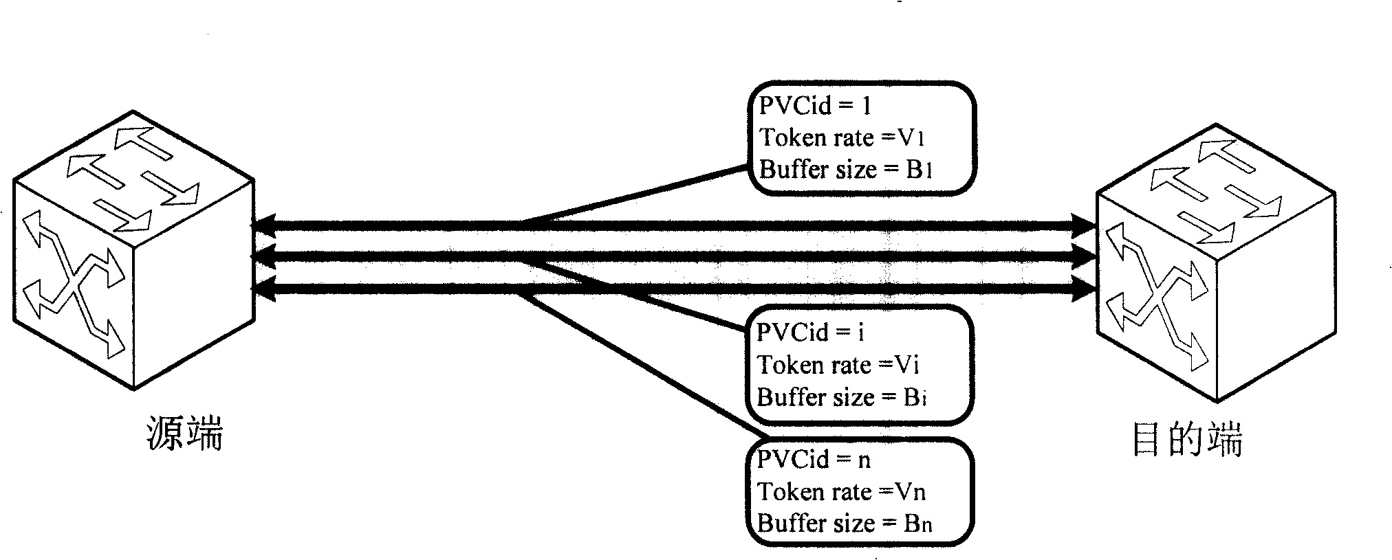
[0067] see figure 2 , is a schematic diagram of a network model in Embodiment 1. Data is transmitted between two endpoint network devices through the PVC data channel. In the figure, the source end sends data packets to the destination end. For example, the physical bandwidth between the two ends is 155Mbps. Each PVC is configured with a label (PVCid) to identify the channel, a corresponding token rate (Token rate), and a configuration Buffer queue capacity (Buffer size), etc., the above configuration parameters can be configured according to the ratio of the predetermined bandwidth allocation. For example, the configuration information of the three PVC channels in the figure are:

[0068] PVCid=1, Token rate=V1, Buffer size=B 1;

[0069] PVCid=i, Token rate=Vi, Buffer size=Bi;

[0070] PVCid=n, Token rate=Vn, Buffer size=Bn.

[0071] In this embodiment, on the basis of the existing ordinary token bucket mechanism, combined with the characteristics of AAL2 itself, the de...

specific Embodiment 2

[0081] Embodiment 1 processes the service data sent in a unified manner, while Embodiment 2 adopts different flow control methods according to the priority of data packets from the perspective of ensuring high-priority service quality.

Embodiment 2

[0082] Embodiment 2 On the basis of Embodiment 1, high-priority messages can properly occupy idle bandwidth, thereby ensuring that high-priority messages can receive priority services; and low-priority messages are only debts in the debt token bucket. Only when the token has been repaid can it participate in scheduling, otherwise it will be cached or even discarded, so as to ensure that high-priority packets participate in scheduling first.

[0083] See Figure 4 , is the flow chart of Embodiment 2. Embodiment two includes:

[0084] Step 401: Check whether the data message is received, if so, execute step 402; otherwise, execute step 411;

[0085] Step 402: Check the CID priority corresponding to the message. For a high-priority message, perform step 403; for a low-priority message, perform step 406;

[0086] Step 403: Check whether there are enough tokens in the common token bucket? If yes, execute step 404; otherwise, execute step 405;

[0087] Step 404: Deduct the corr...


PUM


Abstract

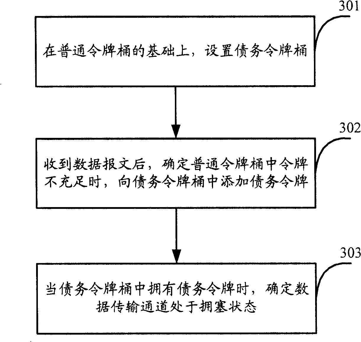
The invention discloses a method for determining congestion status of a data transmission channel, comprising: setting a liability token bucket based on the common bucket; after receiving data telegram, adding liability token in the liability token bucket when determining the tokens in the common token bucket are not adequate; determining the data transmission channel is in congestion status when the liability token bucket has liability token. By using the method, the process flow can be simplified without depending on ATM layer management and being limited by hardware chip; by processing telegram priority, the problem of scheduling data priority can be solved by more flexible means; meanwhile, the invention can be used in other ATM transmission occasions except AAL2, or applied in IP bearing or non-ATM application occasion. The invention also discloses a device for determining congestion status of a data transmission channel.

Description

technical field [0001] The invention relates to the technical field of data flow control, in particular to a method and device for determining the congestion state of a data transmission channel. Background technique [0002] In the data transmission process of an Asynchronous Transfer Mode (Asynchronous Transfer Mode, ATM) network, a token bucket (Token Bucket) mechanism is generally used to implement flow control. [0003] First, a brief introduction to the token bucket principle is given. [0004] The token bucket is a device that regulates the data in the communication flow. The token bucket itself has no discarding or priority policy. On the contrary, the token bucket discards tokens, and when the data flow exceeds a predefined threshold, the transmitted data is processed. traffic management. [0005] The principles followed by the token bucket include: [0006] 1) Tokens are injected into the bucket at a specific rate, and the capacity of the bucket is fixed; [00...

Claims


Application Information

Patent Timeline
Patent Type & Authority Applications(China)
IPC IPC(8): H04L12/56H04L47/6275
Inventor 蓝建栋张健生
Owner DATANG MOBILE COMM EQUIP CO LTD
Learn More