Template early-dismantling device

A formwork and roof technology, applied in the field of formwork early dismantling device, can solve the problems of high construction labor intensity, failure to achieve high and low heights, time-consuming and laborious construction, etc., to speed up construction progress and work efficiency, easy installation and disassembly, and reduce material input Effect

Inactive Publication Date: 2008-09-24
成志全
View PDF0 Cites 15 Cited by
  • Summary
  • Abstract
  • Description
  • Claims
  • Application Information

AI Technical Summary

Problems solved by technology

Such a support structure is not standardized, the lattice size is not easy to guarantee, it is inconvenient to operate, time-consuming and laborious, the function is single, the input of materials is large, the construction effect and economic effect are not good, and more importantly, the U-shaped structure cannot be flexibly adjusted according to needs. The height of the jacking is to make the formwork of the floor and beam reach the level
For this reason, the inventor once designed an assembled double-adjustable multifunctional early dismantling device, which is composed of a column, an adjustment moving mother, a flat support plate and a long bolt rod. Although the height of the U-shaped support can be adjusted, the adjustment The structure is complex, especially when there are beams on the bracket, the moving mother cannot be adjusted arbitrarily, and in fact, the height of the plate and beam support formwork on the bracket cannot be adjusted arbitrarily
[0003] On the other hand, it is too cumbersome to connect the U-shaped jacking to the traditional scaffolding support system in the construction industry. Often, the scaffolding needs to be equipped with fixing bolts to support the U-shaped jacking before it can be used.
This kind of traditional bracket has the disadvantages of large consumption of raw materials, bulky, portable installation, high labor intensity, time-consuming and laborious construction, low construction efficiency and speed, complex structure and poor force. At the same time, after the support system or scaffolding is established , it is impossible to arbitrarily adjust the height of the slab and beam formwork on the bracket, causing great harm to building safety

Method used


Image

  • Template early-dismantling device
  • Template early-dismantling device
  • Template early-dismantling device

Examples


Embodiment Construction

[0019] specific implementation plan

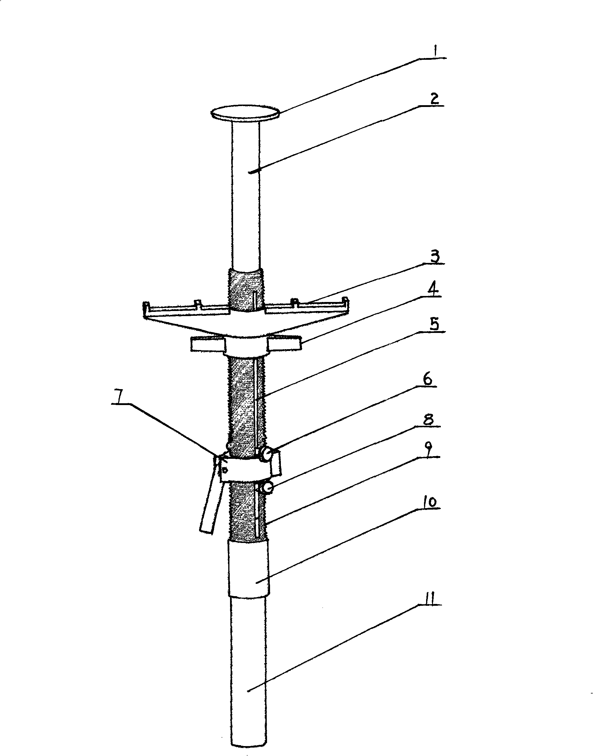
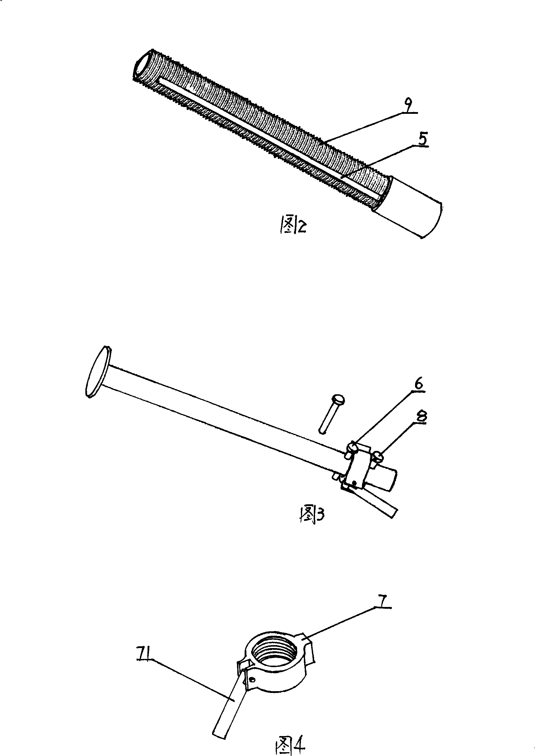
[0020] Such as Figure 1 to Figure 7 As shown, a formwork early removal device is mainly composed of an adjusting threaded pipe, a supporting plate and a supporting plate rod, including the following components:

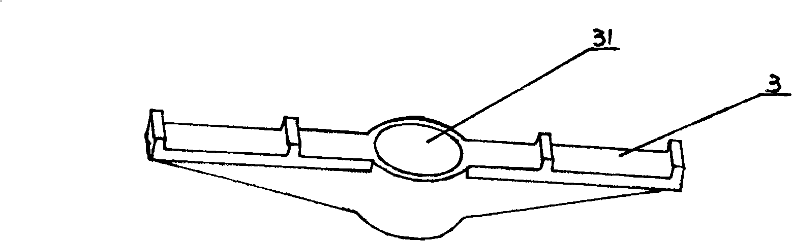
[0021] Adjusting the threaded pipe 9, the outer peripheral wall is an external thread that can be screwed for the bracket adjusting nut 4 and the top plate adjusting nut 7, and the side of the adjusting threaded pipe is provided with a through longitudinal guide groove 5, and the function of the guide groove is for the upper and lower bolts Moving along the guide groove, one end of the adjusting threaded pipe is provided with a socket 10 that can be inserted into the scaffolding pipe, and the external thread part is provided with a bracket 3, a bracket adjusting nut, an upper latch 6 and a top plate adjusting nut in sequence from top to bottom.

[0022] The supporting plate rod 2 is tubular, one end of which is inserted in the a...


PUM


Abstract

The invention belongs to a template early-dismounting device which mainly consists of an adjusting screwed conduit, a splint rod, a bracket, a bracket adjusting nut, a top plate adjusting nut and an upper blocking bolt; the outer surrounding wall of the adjusting screwed conduit is an outer thread for the screw arrangement of the bracket adjusting nut and the top plate adjusting nut; the side of the adjusting screwed conduit is provided with a penetrated longitudinal conduit ferrule; one end of the adjusting screwed conduit is provided with a socket that be inserted by a scaffold tube; the outer thread part is provided with the bracket, the bracket adjusting nut, the upper blocking bolt and the top plate adjusting nut in turn from up to down; the invention can adjust the height of a plate and a beam formwork at any time according to operation requirements and has the advantages of simple structure, convenient use and operation, time and labor saving, safety and reliability, high commonality, convenient checking, easy mounting and dismounting.

Description

technical field [0001] The invention belongs to a formwork early dismantling device, which is used in the field of building construction. Background technique [0002] At present, in the traditional way of supporting formwork for reinforced concrete floors and beams cast on site, U-shaped jacking brackets are generally inserted into the brackets supported by steel pipes and fasteners. The U-shaped jacking supports the main flute, and the secondary flute and formwork . Such a support structure is not standardized, the lattice size is not easy to guarantee, it is inconvenient to operate, time-consuming and laborious, the function is single, the input of materials is large, the construction effect and economic effect are not good, and more importantly, the U-shaped structure cannot be flexibly adjusted according to needs. The height of the jacking makes the formwork of the floor and beam reach the level. For this reason, the inventor once designed an assembled double-adjustab...

Claims


Application Information

Patent Timeline
Patent Type & Authority Applications(China)
IPC IPC(8): E04G11/48E04G25/06
Inventor 成志全
Owner 成志全
Why Eureka
Try Eureka