Loop circuit heat pipe condenser

A loop heat pipe and condenser technology, used in heat exchanger types, indirect heat exchangers, tubular elements, etc., can solve the problems of insufficient condensation area and limited contact area between pipes and fins, and achieve increased area, Increase the effect of the effect

Inactive Publication Date: 2008-09-24
SUN YAT SEN UNIV
View PDF0 Cites 32 Cited by
  • Summary
  • Abstract
  • Description
  • Claims
  • Application Information

AI Technical Summary

Problems solved by technology

But the disadvantage of this method is that the condensation area is not sufficient, and the contact area between the pipe and the fin is very limited

Method used


Image

  • Loop circuit heat pipe condenser
  • Loop circuit heat pipe condenser
  • Loop circuit heat pipe condenser

Examples


Embodiment Construction

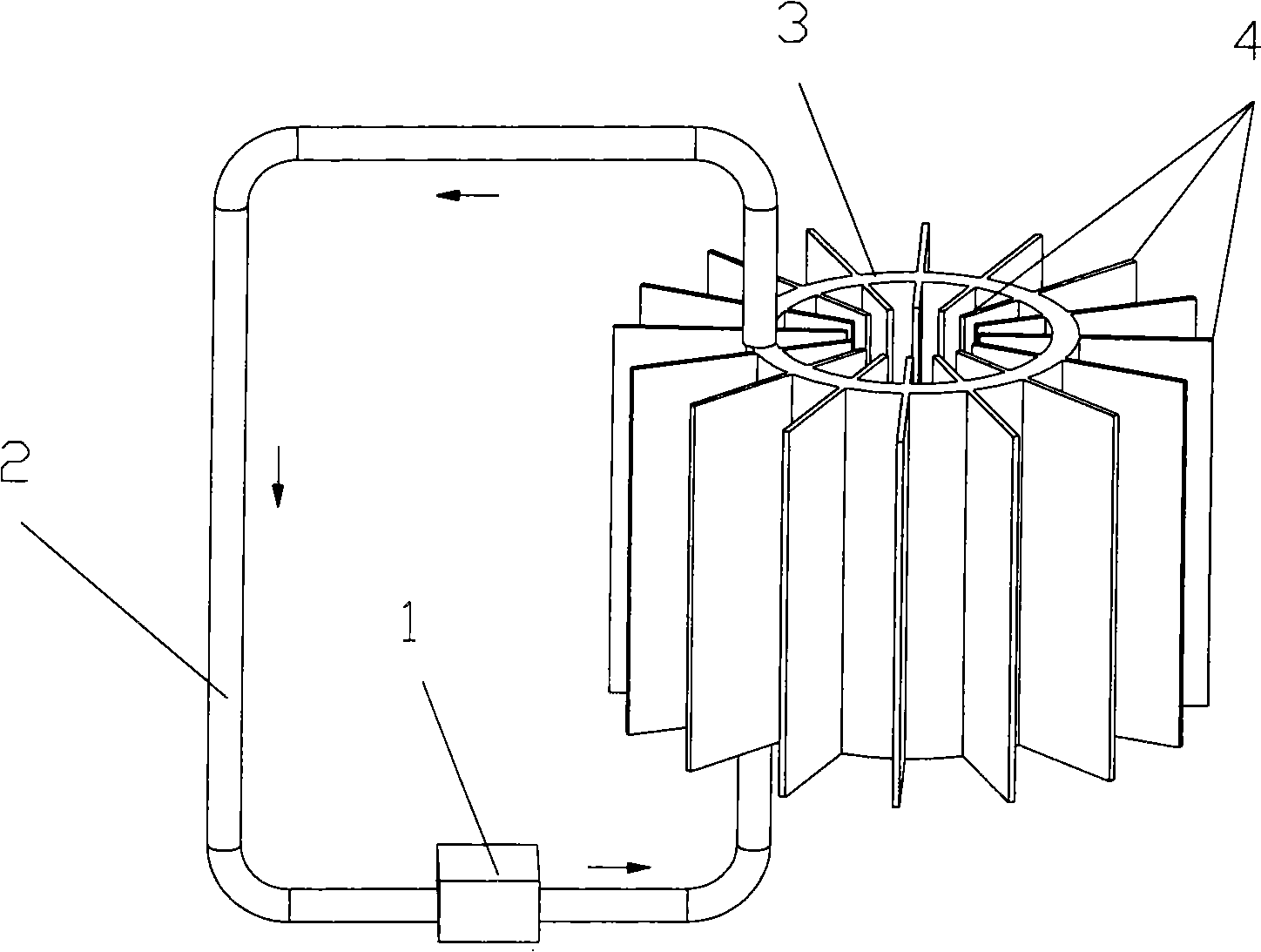
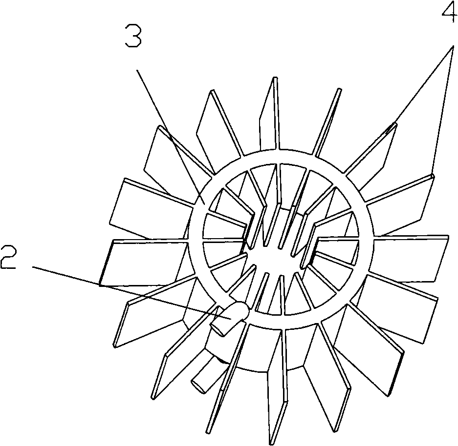
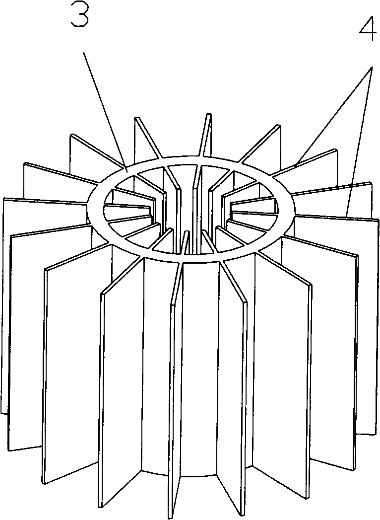
[0016] Such as figure 1 As shown, a loop heat pipe condenser includes an evaporation chamber 1, a pipe 2, and a sealed and hollow condensation chamber 3. Both the condensation chamber 3 and the evaporation chamber 1 are provided with a working fluid inlet and a working fluid outlet, and the evaporation chamber 1 is The outlet of the working medium communicates with the inlet of the working medium on the condensation chamber 3 through the pipeline 2, and the outlet of the working medium on the condensation chamber 3 communicates with the inlet of the working medium of the evaporation chamber 1 through another pipeline 2, and several fins are arranged on the surface of the condensation chamber 3 4. The shape of the condensation chamber 3 is a torus structure.

[0017] The condensation chamber 3 is made of a metal plate material with good thermal conductivity, such as copper, nickel, aluminum, stainless steel or a mixture thereof. The loop heat pipe condenser is filled with wor...


PUM


Abstract

The invention discloses a loop heat pipe condenser, consisting of an evaporation chamber, a heat pipe and a sealed hollow condensation cavity, wherein the condensation cavity and the evaporation chamber are both provided with a working fluid inlet and a working fluid outlet; the working fluid outlet of the evaporation chamber is communicated with the working fluid inlet of the condensation cavity; the working fluid outlet of the condensation cavity is communicated with the working fluid inlet of the evaporation chamber through another pipe; the surface of the condensation cavity is provided with a plurality of fins. The heat pipes of the prior loop heat pipe devices directly extend through the fins; therefore, the condensation effect is not good; especially in case of heat dissipation through natural convection, the cooling effect is very poor. On the basis of the prior loop heat pipe devices, the invention is provided with a condensation cavity, and the evaporation chamber is connected with the condensation cavity through a pipeline; and then fins are arranged on the surface of the condensation cavity, thereby increasing the condensation area of the working fluid; at the same time, the loop structure of the condensation cavity effectively increases the effects of natural convection.

Description

technical field [0001] The invention relates to a loop heat pipe condensation device. Background technique [0002] A loop heat pipe is an efficient heat transfer device that can transfer heat over long distances. There are several main thermal resistances in the heat transfer process of the loop heat pipe: evaporation thermal resistance, transmission thermal resistance, and condensation thermal resistance. In some cases, especially when natural convection is required, the condensation thermal resistance is the most important thermal resistance. If the thermal resistance of this part can be effectively reduced, it will play a vital role in improving the performance of the heat dissipation device composed of the loop heat pipe. [0003] For the heat dissipation of the condensing section of the heat pipe, the way that is often used is to pass the heat pipe through the fins and weld them together. However, the disadvantage of this method is that the condensation area is not ...

Claims


Application Information

Patent Timeline
Patent Type & Authority Applications(China)
IPC IPC(8): F28D15/02
CPCF28D15/0266F28F1/42F28F1/14F28D1/0233
Inventor 吕树申莫冬传
Owner SUN YAT SEN UNIV
Why Eureka
Try Eureka