Coil structure for improving zone-melting radial resistivity uniformity

A technology of resistivity and uniformity, which is applied in the field of coil structure to improve the radial resistivity uniformity of zone melting, can solve the problem of large fluctuation of radial resistivity uniformity of zone melting silicon single crystal, and avoid local electromagnetic field excessive Dense, uniform thickness, reduce the effect of impact

Active Publication Date: 2016-11-09
ZHONGHUAN ADVANCED SEMICON MATERIALS CO LTD +1
View PDF9 Cites 1 Cited by
  • Summary
  • Abstract
  • Description
  • Claims
  • Application Information

AI Technical Summary

Problems solved by technology

[0005] In view of this, the present invention aims to propose a coil structure that improves the radial resistivity uniformity of zone melting, so as to solve the problem of large fluctuations in radial resistivity uniformity of zone melting silicon single crystal in the prior art

Method used


Image

  • Coil structure for improving zone-melting radial resistivity uniformity
  • Coil structure for improving zone-melting radial resistivity uniformity
  • Coil structure for improving zone-melting radial resistivity uniformity

Examples


Embodiment 1

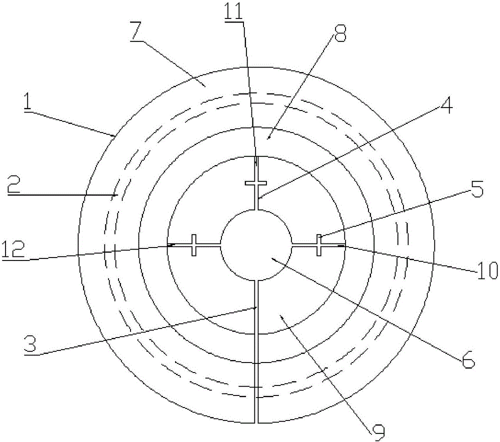
[0036] Such as figure 1 , figure 2 As shown, a coil structure for improving the uniformity of radial resistivity in the molten zone includes a coil main body 1, a cooling water pipe 2, a main slot 3, several auxiliary slots 4 and several transverse slots 5;

[0037] The coil main body 1 is a flat coil, and the upper surface of the coil main body 1 is recessed toward the inside of the coil to form a stepped structure symmetrical about the center; the geometric center of the coil main body 1 is provided with a coil eye 6, and the coil eye 6 is a through hole;

[0038] The cooling water pipe 2 is located inside the outermost step of the coil main body 1 and arranged along the circumference; the inner surface of the cooling water pipe 2 is a mechanochemical polished surface;

[0039] The main seam 3 is radially arranged on the coil body 1 and penetrates the upper surface and the lower surface of the coil body 1; one end of the main seam 3 communicates with the coil eye 6, and t...

Embodiment 2

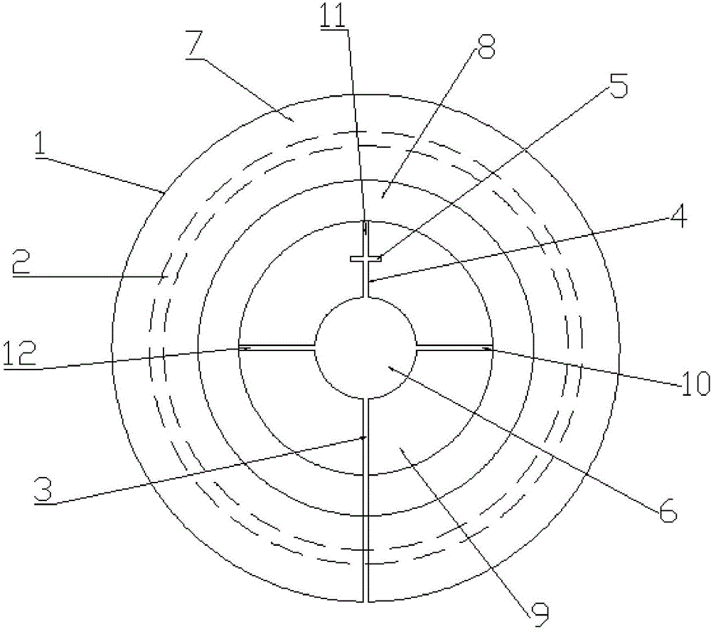
[0051] Such as image 3 As shown, a coil structure for improving the uniformity of radial resistivity in the molten zone includes a coil main body 1, a cooling water pipe 2, a main slot 3, several auxiliary slots 4 and several transverse slots 5;

[0052] The coil main body 1 is a flat coil, and the upper surface of the coil main body 1 is recessed toward the inside of the coil to form a stepped structure symmetrical about the center; the geometric center of the coil main body 1 is provided with a coil eye 6, and the coil eye 6 is a through hole;

[0053] The cooling water pipe 2 is located inside the outermost step of the coil main body 1 and arranged along the circumference; the inner surface of the cooling water pipe 2 is a mechanochemical polished surface;

[0054] The main seam 3 is radially arranged on the coil body 1 and penetrates the upper surface and the lower surface of the coil body 1; one end of the main seam 3 communicates with the coil eye 6, and the other end ...


PUM


Abstract

The invention provides a coil structure for improving the zone-melting radial resistivity uniformity. The coil structure comprises a coil main body, a cooling water pipeline, a main seam, a plurality of sub seams and a plurality of transverse seams, wherein the coil main body is a flat plate coil; the upper surface of the coil main body is sunken into the inside of the coil into a centrosymmetric step structure; a coil hole is formed in the geometric center part of the coil main body; the cooling water pipeline is positioned inside a step at the outermost layer of the coil main body; the main seam is arranged on the coil main body in the radial direction and penetrates through the upper surface and the lower surface of the coil main body; the plurality of sub seams are arranged on the step surface at the innermost layer of the coil main body and penetrate through the upper surface and the lower surface of the step surface; the transverse seams are partially or all arranged on the sub seams; the transverse seams are perpendicular to the respective sub seam. The coil structure for improving the zone-melting radial resistivity uniformity has the advantage that due to the adaption of the technical scheme, the zone-melting silicon single-crystal radial resistivity uniformity can be simultaneously improved.

Description

technical field [0001] The invention belongs to the technical field of zone melting silicon single crystal, and in particular relates to a coil structure for improving the radial resistivity uniformity of zone melting. Background technique [0002] Single crystal silicon growth mainly includes the Czochralski method and the zone melting method. In the process of zone melting silicon single crystal growth, since the single crystal and the melt are not in direct contact with auxiliary materials, almost no other impurities are introduced. At the same time, when the crystal is pulled by the zone melting method, the impurities in the melt volatilize outward through the concentration difference between the melt and the environment in the furnace to achieve the purification effect. Therefore, the quality of the zone melting silicon single crystal is far better than that of the Czochralski silicon single crystal. , It is therefore applied to high-end power electronic devices; howev...

Claims


Application Information

Patent Timeline
Patent Type & Authority Applications(China)
IPC IPC(8): C30B13/20C30B29/06H05B6/36H05B6/42
CPCC30B13/20C30B29/06H05B6/36H05B6/42
Inventor 娄中士王遵义刘铮由佰玲张雪囡李立伟乔柳
Owner ZHONGHUAN ADVANCED SEMICON MATERIALS CO LTD
Why Eureka
Try Eureka