
Lead frame

A technology of lead frame and lead, which is applied in the direction of electrical components, electric solid devices, circuits, etc., can solve the problems of insufficient flexibility and single shape, and achieve the effect of improving flexibility

Active Publication Date: 2008-09-24
SEMICON MFG INT (SHANGHAI) CORP
View PDF1 Cites 1 Cited by
  • Summary
  • Abstract
  • Description
  • Claims
  • Application Information

AI Technical Summary

Problems solved by technology

However, since the through holes on the existing die pad generally adopt a square structure and a single shape, the flexibility in the manufacturing process is not enough

Method used


Image

  • Lead frame
  • Lead frame
  • Lead frame

Examples


Embodiment Construction

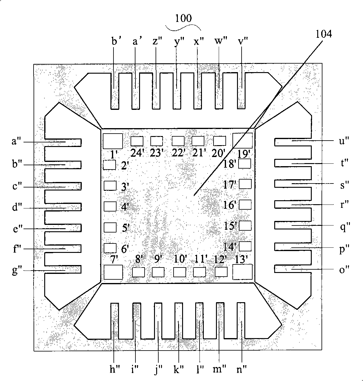
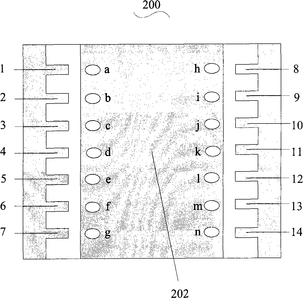
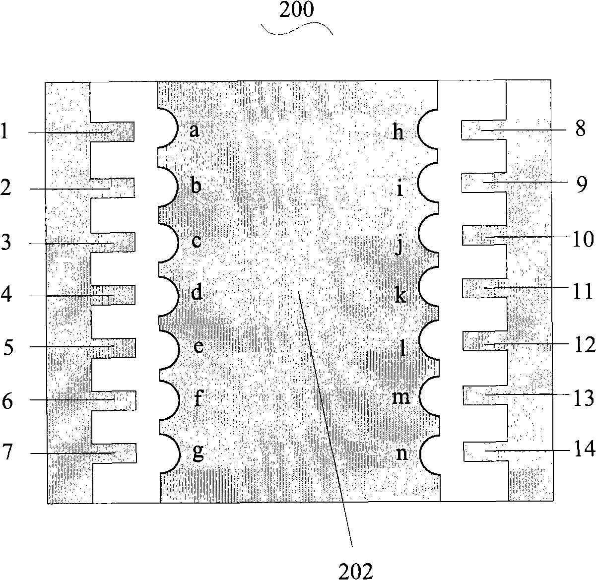
[0023] The lead frame of the prior art is a single-layer structure, and there are through holes on the die pad, and the through holes are located at the edge of the die pad, so that the subsequent chips installed on both sides of the die pad can be placed in the same direction, so the two sides of the die pad The internal wiring of the chip on the side is symmetrical, which simplifies the packaging process of the semiconductor chip. However, since the through holes on the existing die pad generally adopt a square structure and a single shape, the flexibility in the manufacturing process is not enough. The shape of the through hole on the die pad of the present invention can be a regular or irregular polygon, wherein the sides of the polygon can be linear, arc or a mixture of linear and arc. The flexibility and effect of the manufacturing process are improved. The specific implementation of the present invention will be described in detail below in conjunction with the accompa...


PUM


Abstract

A lead frame comprises a tube core pad and a lead located around the tube core pad. The tube core pad is provided with a through hole, and the through hole is located at the edge of the tube core pad. The through hole is used for leading a melt wire which is connected with the lead to go through. The shape of the through hole can be a regular or irregular polygon, wherein sides of the polygon can be line shape, arch or mix of line shape and arch. The structure improves flexibility of manufacture process.

Description

technical field [0001] The invention relates to the field of semiconductor chip packaging, in particular to a lead frame used in the semiconductor chip packaging process. Background technique [0002] As the demand for miniaturization, light weight and multi-functionalization of electronic components increases day by day, the packaging density of semiconductors increases continuously. Therefore, it is necessary to reduce the size of the package and the area occupied by the package. Among the technologies developed to meet the above requirements, the multi-chip semiconductor packaging technology plays an indicative role in the overall cost, performance and reliability of packaged chips. [0003] In the process of packaging a semiconductor chip, it is necessary to electrically connect the semiconductor chip with an external circuit with a lead frame to provide the external circuit with functions performed by the semiconductor chip, and the lead frame may also physically suppor...

Claims


Application Information

Patent Timeline
IPC IPC(8): H01L23/495
CPCH01L2924/0002
Inventor 王津洲
Owner SEMICON MFG INT (SHANGHAI) CORP
Learn More