Vehicle brake, in particular caliper brake

A caliper brake, vehicle braking technology, applied in the direction of brakes, brake types, brake components, etc., can solve problems such as strong self-locking effect and influence

Inactive Publication Date: 2008-09-24
LUCAS AUTOMOTIVE GMBH
View PDF1 Cites 31 Cited by
  • Summary
  • Abstract
  • Description
  • Claims
  • Application Information

AI Technical Summary

Problems solved by technology

Longer delays are therefore to be avoided, which could adversely affect e.g. drive-away operations
But what the prior art cited above offers, especially in the case of high parking brake forces, even additionally requires hydraulic assistance to release the parking brake, since usually the electric motor drive of the parking brake is not strong enough to overcome the Self-locking effect caused by parking brake force

Method used


Image

  • Vehicle brake, in particular caliper brake
  • Vehicle brake, in particular caliper brake
  • Vehicle brake, in particular caliper brake

Examples


Embodiment Construction

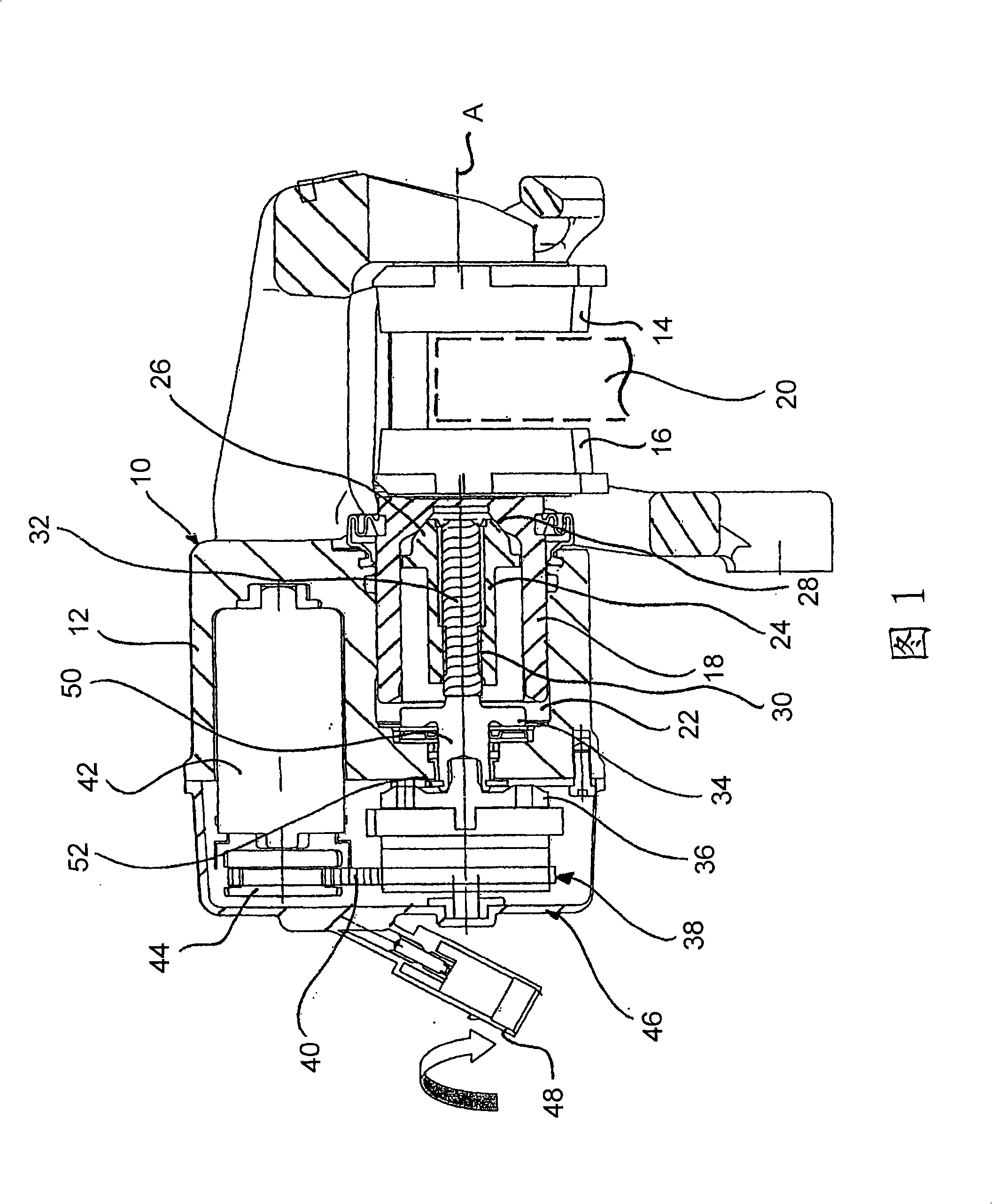
[0016] In FIG. 1 , a vehicle brake according to the invention is generally indicated by 10 . The vehicle brake 10 takes the form of a caliper brake. It comprises a housing 12 in which two brake pads 14 and 16 are accommodated on the principle of a floating caliper. The brake pads 16 are movable by the brake piston 18 along the axis A towards the brake disc 20 indicated only by dashed lines.

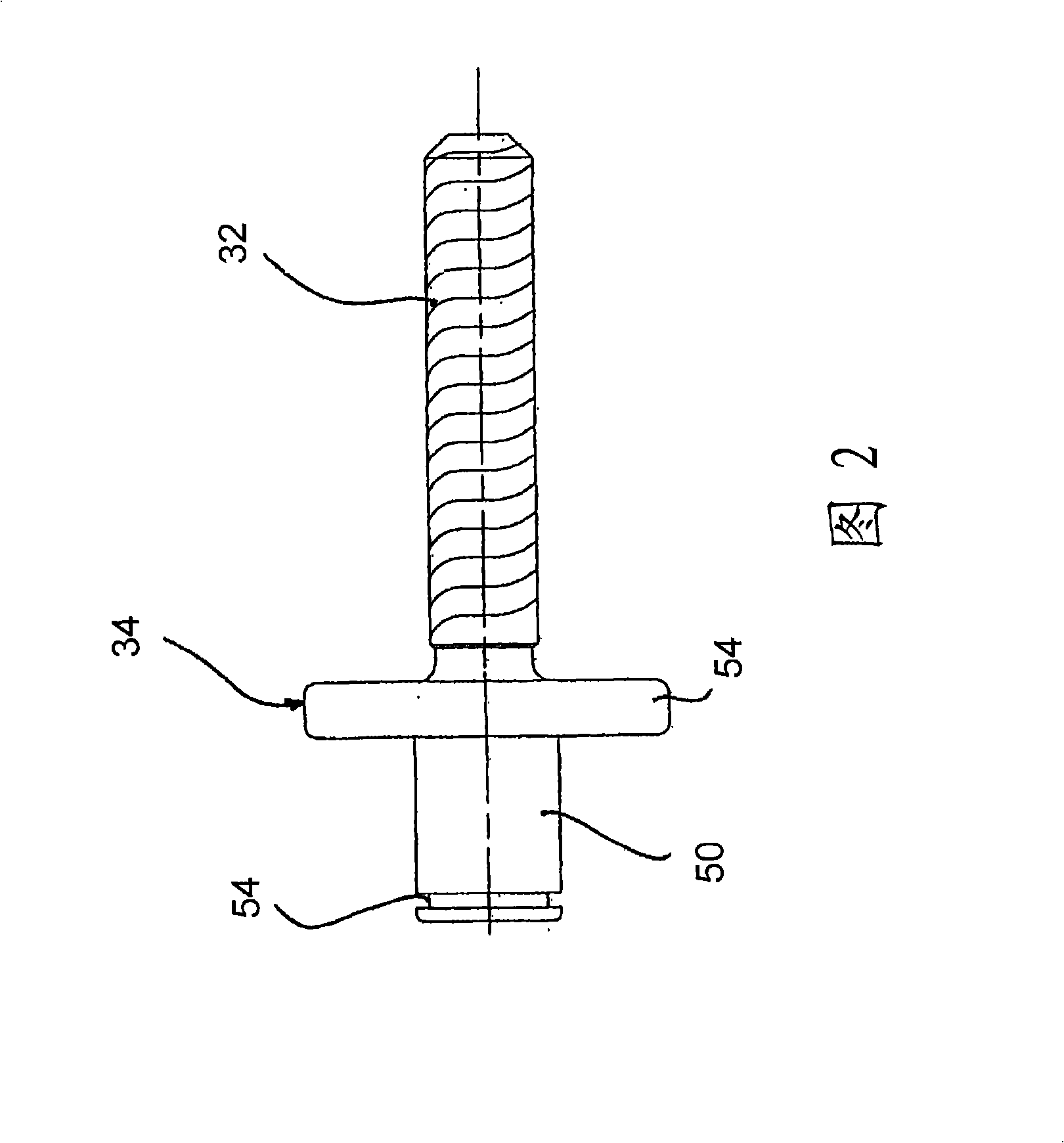
[0017] The brake piston 18 and the housing 12 enclose a hydraulic chamber 22 . The brake piston 18 is hollow in design. A nut arrangement 24 with a conical head 26 is accommodated in the brake piston 18 . The tapered head 26 can be used for locking engagement with a complementary designed tapered portion 28 inside the brake piston 18 . Furthermore, the nut arrangement 24 is accommodated in a rotationally fixed manner in the linearly displaceable brake piston 18 . The nut device 24 is likewise hollow and provided with a threaded portion 30 . A lead screw 32 is provided in the threade...


PUM


Abstract

The invention relates to a vehicle brake (10), in particular caliper brake, having a housing (12), having a brake piston (18), which is held in the housing (12) and is linearly displaceable relative thereto, for displacing a brake lining (16), and having a mechanical actuator arrangement for displacing the brake piston (18), wherein the brake piston (18) in the housing (12) can be displaced by filling a hydraulic chamber (22) via a hydraulic brake circuit, and wherein the mechanical actuator arrangement has a threaded spindle (32) which is rotatably mounted in the housing (12) and can be driven in rotation, wherein the brake piston (18) can be displaced linearly relative to the housing (12) as a result of a rotary movement of the threaded spindle (32).; In said vehicle brake, it is provided according to the invention that the threaded spindle (32) is provided with a multiple-start self-locking thread with n flights, wherein the number n and the thread pitch are selected such that the thread is close to the self-locking limit.

Description

technical field [0001] The present invention relates to vehicle brakes, and in particular to caliper brakes, having a housing, a brake piston housed in the housing and movable linearly relative to the housing to move a brake pad, and a brake piston for moving the brake piston A mechanical actuation device, wherein the brake piston is movable in a housing by filling a hydraulic cavity with a hydraulic brake circuit, and wherein the mechanical actuation device comprises a lead screw rotatably mounted in the housing and rotatably arranged, wherein due to The lead screw rotates and the brake piston moves linearly relative to the housing. Background technique [0002] Such a brake is known, for example, from document WO 2005 / 073043 A1. In such a vehicle brake, during a service brake operation, by filling a hydraulic chamber with hydraulic fluid, a brake piston moves within a housing to move a brake pad toward a brake disc and achieve a braking effect. To obtain a parking brake ...

Claims


Application Information

Patent Timeline
Patent Type & Authority Applications(China)
IPC IPC(8): F16D65/16F16D65/21F16D65/18
CPCF16D65/18B60T13/741F16D2121/02F16D2121/24F16D2123/00F16D2125/40F16D2127/06F16D2129/10
Inventor 莱奥·吉勒斯
Owner LUCAS AUTOMOTIVE GMBH
Why Eureka
Try Eureka