Vehicle brake system

A technology for vehicle braking and wheel braking, which is applied to brakes, vehicle components, brake transmissions, etc., and can solve problems such as changes in the brake pedal, the difference between the brake pedals becomes larger, and the driver feels uncomfortable.

Inactive Publication Date: 2008-10-01
ADVICS CO LTD
View PDF7 Cites 40 Cited by
  • Summary
  • Abstract
  • Description
  • Claims
  • Application Information

AI Technical Summary

Problems solved by technology

Adjusting the controlled hydraulic braking force involves adjusting the operation of the pump that generates the controlled hydraulic pressure for the controlled hydraulic braking force, which causes the brake fluid from the master cylinder to be consumed by the pump, so that the stroke of the brake pedal inevitably changes
When the regenerative braking force increases, the difference in brake pedal travel becomes larger, which may make the driver feel uncomfortable
These problems arise naturally since brake-by-wire is not implemented in the vehicle braking device described in the last-mentioned US Bulletin

Method used


Image

  • Vehicle brake system
  • Vehicle brake system
  • Vehicle brake system

Examples


no. 1 approach

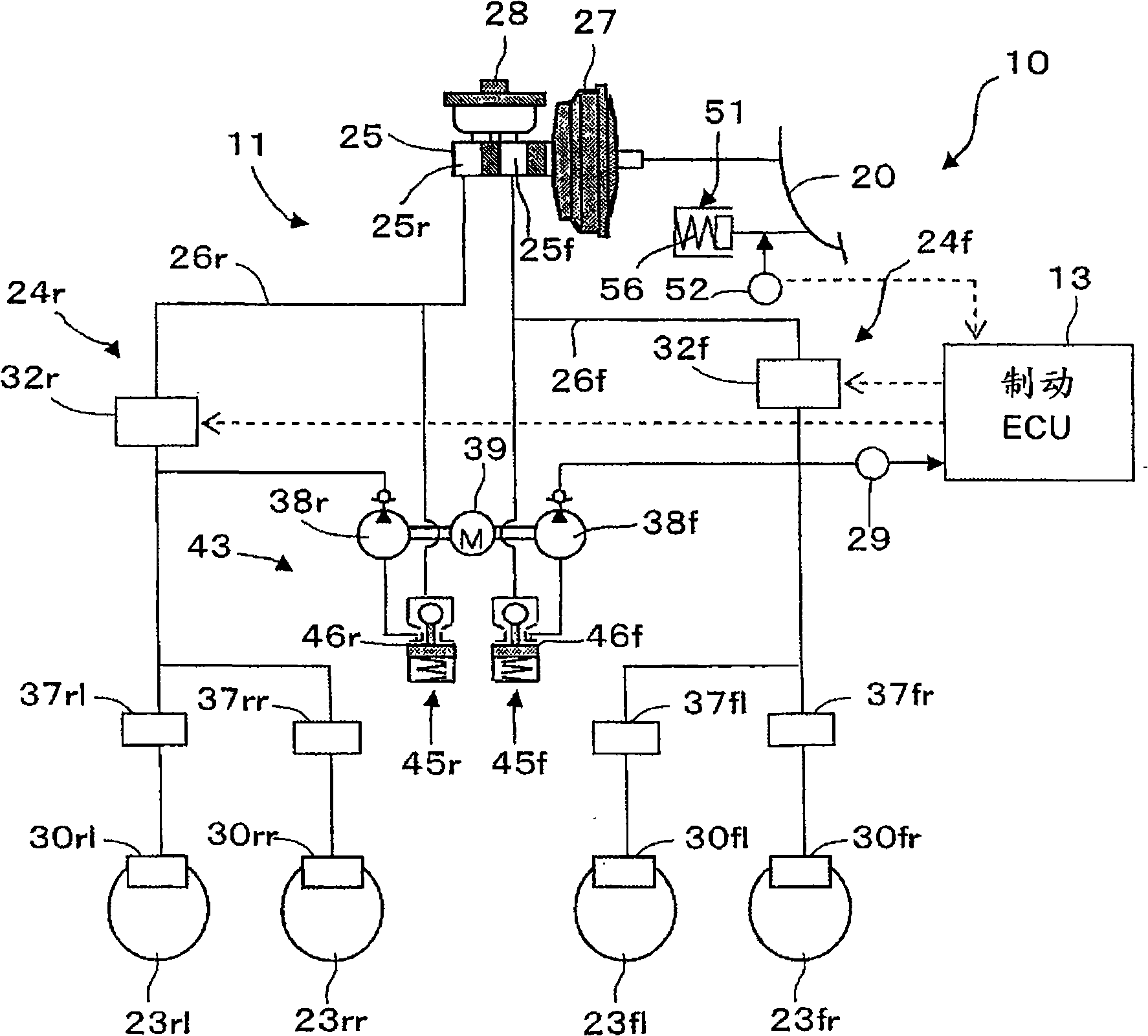
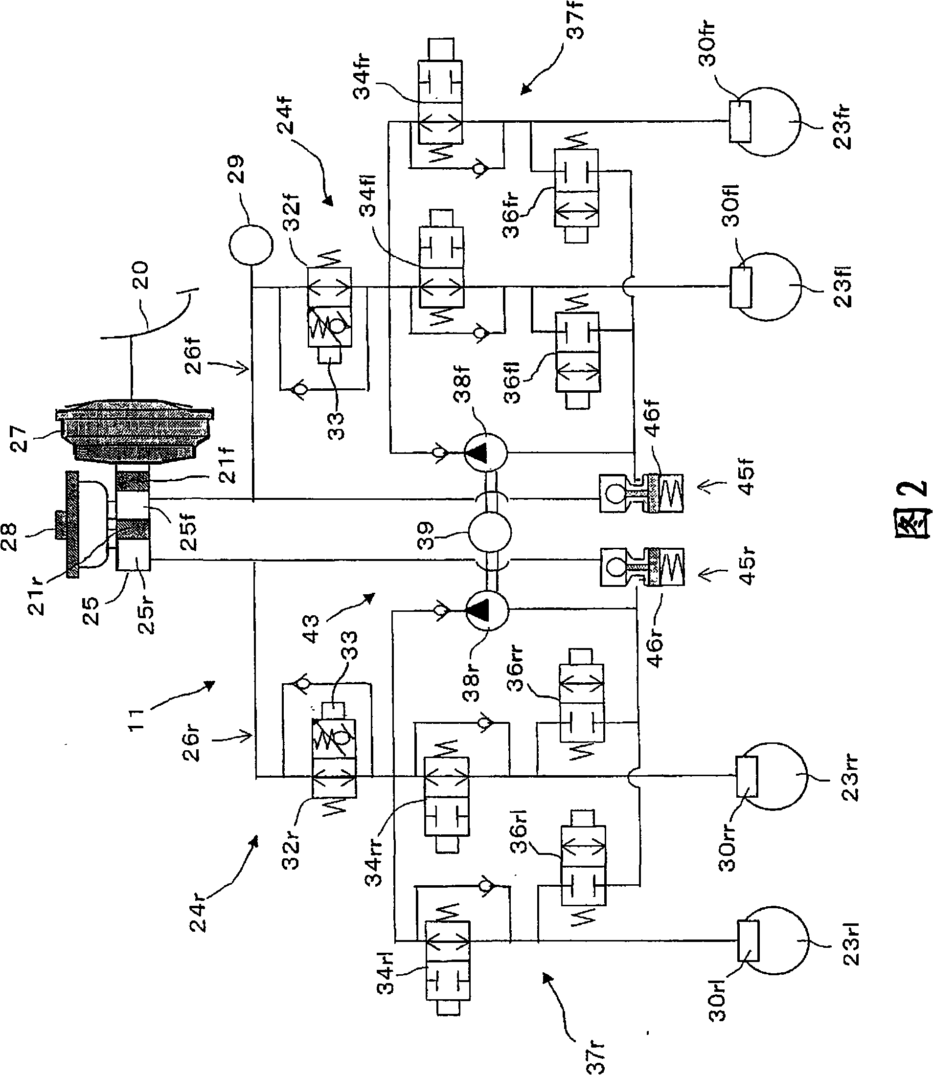
[0030] Hereinafter, a brake system of a brake-by-wire type vehicle according to a first embodiment of the present invention will be described with reference to the accompanying drawings. See now figure 1 2, the vehicle brake system generally designated by the reference numeral 10 includes a hydraulic brake device 11, an ECU 13 for controlling the hydraulic brake device 11 and the like.

[0031]The hydraulic brake device 11 is provided with a left front wheel brake 30fl and a right front wheel brake 30fr for the left front wheel 23fl and right front wheel 23fr, and a left rear wheel brake 30rl and right rear wheel for the left rear wheel 23rl and the right rear wheel 23rr Wheel brake 30rr. As is well known in the art, each of these brakes 30fl, 30fr and 30rl, 30rr is a disc brake or drum brake including at least one brake cylinder for operating brake shoes to limit the Rotation of a brake disc or a brake drum that rotates with the tire (none of them are shown). The configurations ...

no. 2 approach

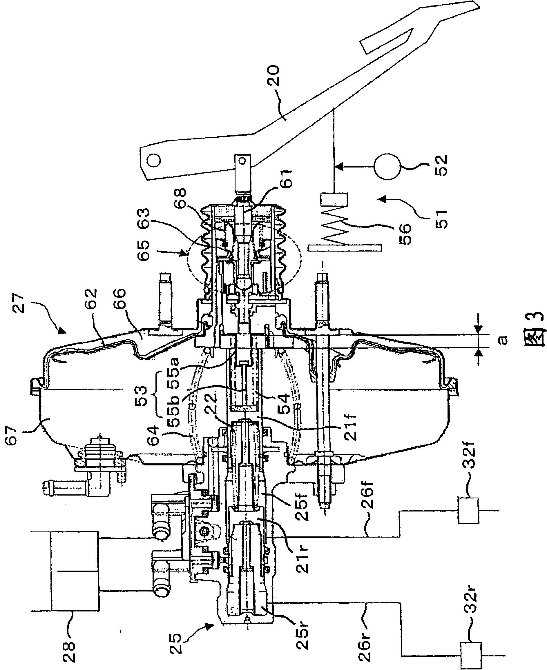
[0058] Fig. 6 shows certain components that are features of a vehicle brake system according to a second embodiment of the present invention. The brake system of the second embodiment differs from the brake system of the first embodiment described above in that a fluid absorbing mechanism 153 is used instead of the stroke absorbing mechanism 53 including a spring 54 and suspension members 55a, 55b, and a rubber disc 69 The utility model is used to restore the reaction force to the brake pedal 20 so that the device with the existing structure can be used as the vacuum-type booster device 27. Therefore, the components that are different from the components in the first embodiment will be described below. The components that are identical or identical to the components in the first embodiment are marked with the same reference numerals in FIG. 6, and these components will not be referred to here. Give a detailed description.

[0059] As shown in FIG. 6, the fluid absorption mechanism...

no. 3 approach

[0063] Figure 7 A partial circuit that is a feature of the vehicle braking system according to the third embodiment of the present invention is shown. The brake system of the third embodiment differs from the brake system of the second embodiment described above only in that a restriction member 70 for restricting the flow of fluid absorbed by the fluid absorption mechanism 153 is added to the inlet side of the fluid absorption mechanism 153 as Free parts or blank parts. The restricting member 70 includes a fixed throttle valve 71 and a check valve 72 connected in parallel with the fixed throttle valve 71. The check valve 72 is used to allow fluid to flow only from the cylinder 57 to the passage 26r.

[0064] In the braking system of the third embodiment, when the driver suddenly performs a braking operation, the restricting member (throttle member) 70 restricts the amount of brake fluid flowing into the cylinder 57, which results in restricting the absorption of the fluid absor...


PUM


Abstract

A vehicle brake system, capable of realizing a brake-by-wire construction which can be installed in vehicles in the same manner as conventional brake systems, is provided with a booster device, a master cylinder, wheel brakes, and a hydraulic pressure control device interposed between the master cylinder and the wheel brakes. The system is further provided with a stroke sensor for detecting the moving stroke of a brake pedal, a simulator for applying to the brake pedal a pseudo reaction force corresponding to the moving stroke of the brake pedal, a play or idling component arranged between the booster device and the hydraulic pressure control device for absorbing the moving stroke of the brake pedal by a predetermined amount, and an electronic control device for controlling the hydraulic pressure control device based on an input from the stroke sensor.

Description

[0001] Reference binding [0002] This application is based on the Japanese application No. 2007-080725 filed on March 27, 2007 and the Japanese application No. 2008-022420 filed on February 1, 2008 and claims the priority of the application under 35U.SC119, which The entire content of the application is incorporated herein by reference. Technical field [0003] The present invention relates to a vehicle brake system capable of realizing brake-by-wire movement, wherein a brake operating part is connected to a brake operating part through an electric signal. Background technique [0004] In the so-called "brake-by-wire system", the brake operating part including the brake pedal and the brake operating part including wheel brakes are connected to each other by means of electrical signals, and the brake operating part is mechanically isolated from the brake operating part Therefore, when the braking force changes based on, for example, an anti-lock braking operation, unpleasant vibra...

Claims


Application Information

Patent Timeline
Patent Type & Authority Applications(China)
IPC IPC(8): B60T13/74
Inventor 桥田浩一森川裕介内藤政行小久保浩一
Owner ADVICS CO LTD
Why Eureka
Try Eureka