Hot-wire anemometer calibration apparatus and method in acoustic field

A technology of hot wire anemometer and calibration device, which is applied in the direction of electric power measurement and series vibration meter by thermal method, which can solve the problems of limiting the calibration range, increasing the difficulty and uncertainty of calibration, and achieving a large speed range and accurate measurement. Effect

Inactive Publication Date: 2008-10-01
TECHNICAL INST OF PHYSICS & CHEMISTRY - CHINESE ACAD OF SCI
View PDF0 Cites 17 Cited by
  • Summary
  • Abstract
  • Description
  • Claims
  • Application Information

AI Technical Summary

Problems solved by technology

However, when the calibrated flow rate exceeds a certain range, the sound field will show nonlinear characterist...

Method used


Image

  • Hot-wire anemometer calibration apparatus and method in acoustic field
  • Hot-wire anemometer calibration apparatus and method in acoustic field
  • Hot-wire anemometer calibration apparatus and method in acoustic field

Examples


Embodiment 1

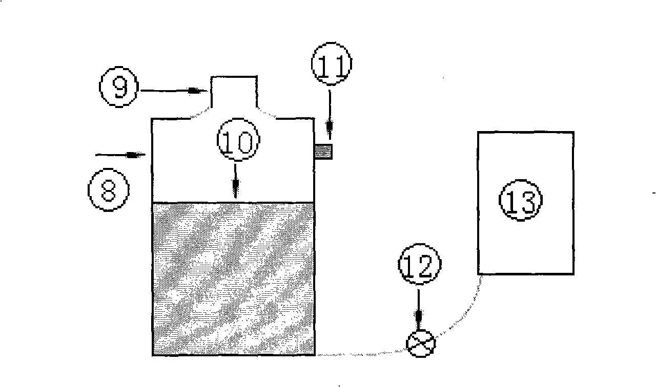
[0043] Such as Figure 4 As shown, the hot wire anemometer in the sound field of the present invention is a device using a moving probe calibration method, mainly comprising: a pressure-bearing airtight container 14 with a fluid working medium input valve and an output valve; The hot-wire probe 4 of the hot-wire anemometer is a driving device 16 that moves in the airtight container, and the driving device 16 fixes and drives the probe 4 to move through a guide rod device 15 thereon; it is used to sense the reciprocating motion of the probe 4 The displacement sensor installed on the driving device for speed; the pressure sensor and temperature sensor installed on the airtight container to measure the pressure and temperature of the working medium in the airtight container.

[0044] In addition to designing the size of the airtight container 14 according to the volume of the parts placed in the container, it is also necessary to take into account the disturbance of the moving pa...

Embodiment 2

[0051] Such as Figure 5 As shown, the hot-wire anemometer in the sound field of the present invention is a device using a moving probe calibration method, which is different from Embodiment 1 in that: Figure 5 As shown, the present embodiment is semi-closed, and the driving device 16 is placed outside the sealed container 14, and the hot wire probe 4 is placed in the sealed cavity 14 through the guide rod 15. Dynamic sealing is performed, for example, by means of a dynamic sealing mechanism 18 . The advantage of the semi-closed type is that the moving parts in the closed chamber are only the probe and the guide rod device, so the volume is small, but the requirements for dynamic sealing are increased, and when the container is filled with high pressure, the drive mechanism is increased. differential pressure load. In Embodiments 1 and 2, both the pressure sensor and the temperature sensor can be installed on the wall of the airtight container. Others are the same as embod...


PUM


Abstract

The present invention discloses a hot-wire anemometer calibrating device in a sound filed and a calibrating method. The device comprises the following components: a closed container; a driving mechanism which is fixed and installed in the closed container; a probe which is connected with the driving mechanism and moves under the driving of the driving mechanism; a displacement transducer which is provided on the driving mechanism; a pressure sensor and a temperature sensor which are installed at the inner part of the container; and a conducting wire. The method comprises the following procedures: when the closed container is executed with vacuum pumping, filling a working medium to be tested; setting a first group of working condition point; setting a second group of working condition point; respectively collecting a hot-wire electric signal corresponding with the working condition point to the first group of working condition point and the second working condition point; respectively executing data fitting to the first group of working condition point, the second group of working condition point and the corresponding hot-wire electric signals; and fitting the two obtained data and then executing combination fitting. The calibrating to the hot-wire anemometer is more accurate and a larger speed range can be calibrated.

Description

technical field [0001] The invention mainly relates to fluid velocity measurement, in particular to a hot wire anemometer (Hot Wire Anemometry) calibration device and a calibration method for measuring medium velocity in a sound field. Background technique [0002] The hot wire anemometer is an instrument used to measure the velocity of the flow field. The commonly known velocity sensing element is a hot wire or hot film welded between two fork rods. The material is usually tungsten or platinum metal. The following collectively referred to as the Hotline in the description. According to the number of sensing elements on the probe, that is, hot wires, such as 1-3, single-point one-dimensional to three-dimensional velocity measurement of the flow field can be performed. figure 1 The structure of a one-dimensional probe is shown. There are two fork bars 2 at one end of the probe, and a hot wire 1 is installed between the two fork bars 2. The other end of the probe has a pin 3 ...

Claims


Application Information

Patent Timeline
IPC IPC(8): G01R21/02G01R5/10
Inventor 戴巍陈燕燕罗二仓吴张华
Owner TECHNICAL INST OF PHYSICS & CHEMISTRY - CHINESE ACAD OF SCI
Why Eureka
Try Eureka